RoboPhery Documentation
Internet of Things is growing phenomena caused by advances of speed and size of computational hardware. It is possible to collect data from various sensors, devices or services and react to evaluated envent and start the predefined process. These systems are closely connected with Cloud based services as they provide publicly accesible interface for management and visualization, coputational and storage cababilities for forecasts and other advanced data processing to create ambient intelligence environment. The true ambient environments react to the presence of people and the sensors and actuators have become part of the environment.
This article shows the design and implementation of Python library for interfacing low level hardware sensors and actuators with MQTT and TSDB bindings. The system architecture is designed to be so simple at hardware level to support sigle-board microcontrollers like ESP2866, ESP32 modules as well as sigle-board computers based on ARM or x86 architectures. The communication among devices is handled by the standard MQTT message bus.
Chapter 1. Project Overview
Introduction
This paper shows possible utilization of inexpensive Linux and MicroPython compatible microcontrollers, hardware actuators and sensors to create fully autonomous and isolated agent-based platform. This platform can perform wide range automation use cases. These range from simple environmental automations, surveillance, to complete ambient intelligence environments.
First chapter introduces global architecture of autonomous agents with communication protocols for messages to the overlaying event driven controllers, dashboards or any other services. These systems use scalable and modular architecture to minimise the computational overhead which allows efficient use of available hardware resources.
The next part covers the autonomous agents in more details. Models of hardware interfaces and corresponding modules. It also covers description of the virtual modules that provide the simple thresholds or fuzzy logic reasoning for autonomous control.
The final chapter shows simple interaction with overlay control system that can communicate with multiple autonomous systems, gather vital information and even publish arbitrary actions on demand.
The control system contains time-series database, dashboard and reasoning platform which can detect hardware malfunctions of autonomous agent systems and perform necessary steps to repair it. With the usage of virtual models that provide high-level access to individual physical modules of individual agents.
Architecture
RoboPhery project provides software drivers for a wide variety of commonly used sensors and actuators through both wired and wireless interfaces. Platform is designed for multiple interfaces to be stacked (GPIO, I²C or SPI over IQRF or BlueTooth) to provide seamless intergration with vast variery of hardware platforms. The software drivers interact with the underlying hardware platform (or microcontroller), as well as with the attached sensors, through API calls to the interfaces.
The actuators are controlled and the data is collected and this together forms a hardware foundation for ambient intelligence environment. The event-driven control system, data storage and data processing systems are provided in form of external cloud services or handled by computer with more processing power.
Ambient intelligence environments that are those that are sensitive and responsive to the presence of people. A typical example of ambient intelligence environment is a Home environment [1]. Term Ambient intelligence as a vision of the future of consumer electronics and computing was originally pointed by Eli Zelkha at Palo Alto Ventures in the late 1990s. The time frame set for this vision was 2010–2020.[1][2][3][4]
In an ambient intelligence world, devices work together to support people in their everyday life activities, tasks and rituals in a natural way that uses information from physical environment collected by network connected devices and uses cloud power to drive the intelligence that can react and learn to the information coming from the environment.
The physical devices steadily grow smaller and are more integrated into our environment, the technology used disappears until only the user interface remains visible to the users.
The ambient intelligence paradigm builds upon pervasive computing, ubiquitous computing, profiling, context awareness, and human-centric computer interaction design and is characterized by systems and technologies that are (Zelkha et al. 1998; Aarts, Harwig & Schuurmans 2001):
- Embedded
- Many networked devices are integrated into the environment
- Context aware
- These devices can recognize you and your situational context
- Personalized
- They can be tailored to your needs
- Adaptive
- They can change in response to you
- Anticipatory
- They can anticipate your desires without conscious mediation.
The basic architecture setup consists of time-series database, user dashboard and event-driven control engine. This setup can be further expanded by machine learning services. Actual RoboPhery application is writtern in Python code compatible with MicroPython used on less expensive microcontrollers.
Ambient Inteligence System
On the following Figure, you can see components of our proposed ambient intelligence system and their relationships. The central component is the message bus, in our case provided by MQTT broker.
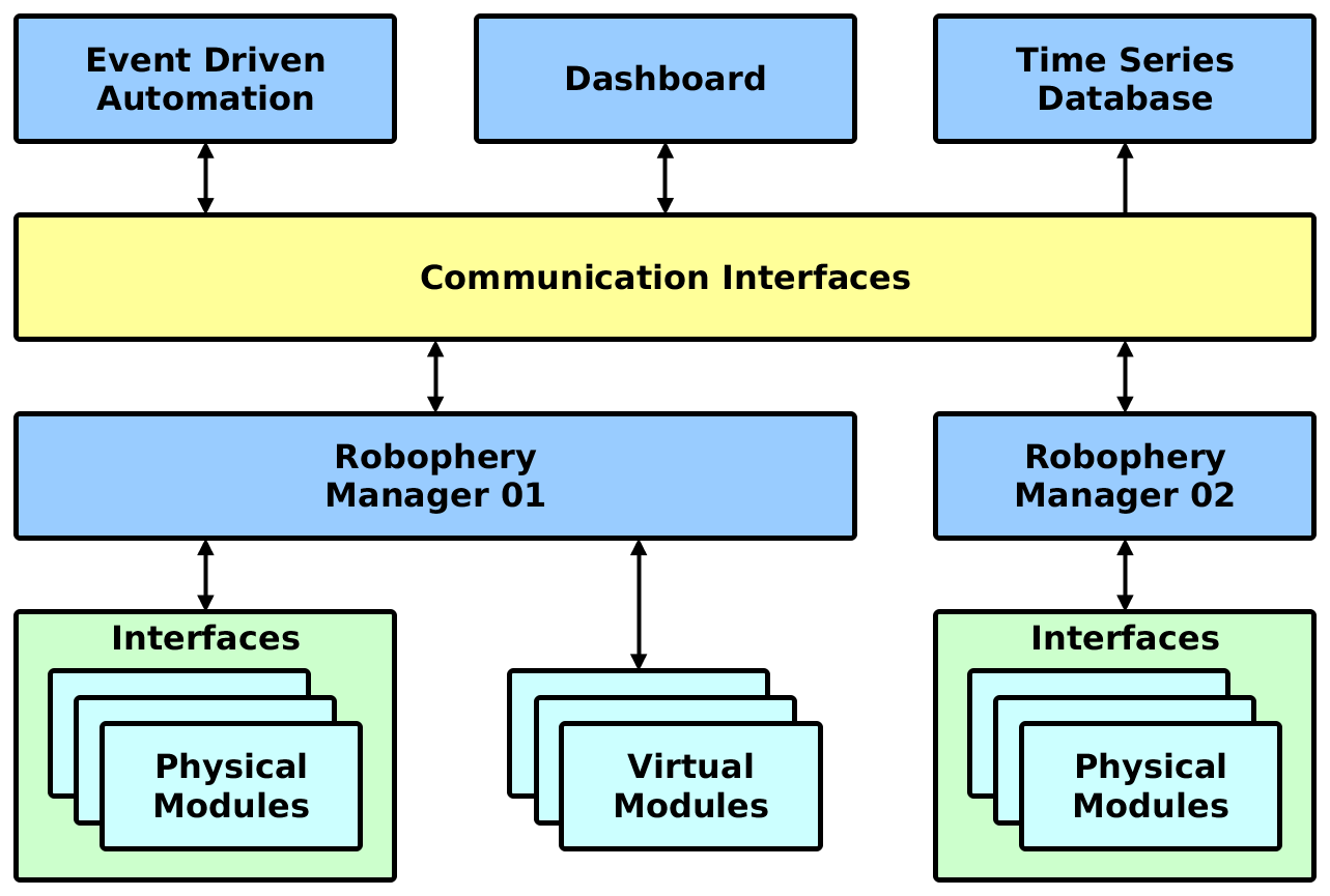
The event driven automation plays key role in controlling the behavior of the system, the inner conditions are altered by machine-learning algorithms that can provide better values to get the best outcome where entropy is involved. Virtual models can provide future models for autonomous decisions based on past conditions or predefined conditions. This mechanism is used control the autonomous agent if communication bus is broken.
Communication Bus
MQTT is a machine-to-machine connectivity protocol in area of “Internet of Things”. It was designed as an extremely lightweight publish/subscribe messaging transport. It is useful for connections with remote locations where a small code footprint is required and/or network bandwidth is low. MQTT broker can handle thousands of messages per second, supports high-availability setups for both high performance and stability. Individual Autonomous agents and cloud-based Control system along with time-series databases are connected to this common message bus.
Event-driven Controller
Event-driven architecture (EDA), also known as message-driven architectures, is a software architecture pattern promoting the production, detection, consumption of, and reaction to events.
An event can be defined as a significant change in state[1]. For example, when a user turn’s on a switch, the swith’es state changes from “off” to “on”. A car dealer’s system architecture may treat this state change as an event whose occurrence can be made known to other applications within the architecture. From a formal perspective, what is produced, published, propagated, detected or consumed is a (typically asynchronous) message called the event notification, and not the event itself, which is the state change that triggered the message emission. Events do not travel, they just occur. However, the term event is often used metonymically to denote the notification message itself, which may lead to some confusion.
Time-series Database
A time series database (TSDB) is optimized for handling time series data storage and retrieval, arrays of numbers indexed by time (a datetime or a datetime range). In some fields these time series are called profiles, curves, or traces. A time series of stock prices might be called a price curve. A time series of energy consumption might be called a load profile. A log of
Despite the disparate names, many of the same mathematical operations, queries, or database transactions are useful for analysing all of them. The implementation of a database that can correctly, reliably, and efficiently implement these operations must be specialized for time-series data.
TSDBs are databases that are optimized for time series data. Software with complex logic or business rules and high transaction volume for time series data may not be practical with traditional relational database management systems. Flat file databases are not a viable option either, if the data and transaction volume reaches a maximum threshold determined by the capacity of individual servers (processing power and storage capacity). Queries for historical data, replete with time ranges and roll ups and arbitrary time zone conversions are difficult in a relational database. Compositions of those rules are even more difficult. This is a problem compounded by the free nature of relational systems themselves. Many relational systems are often not modelled correctly with respect to time series data. TSDBs on the other hand impose a model and this allows them to provide more features for doing so.
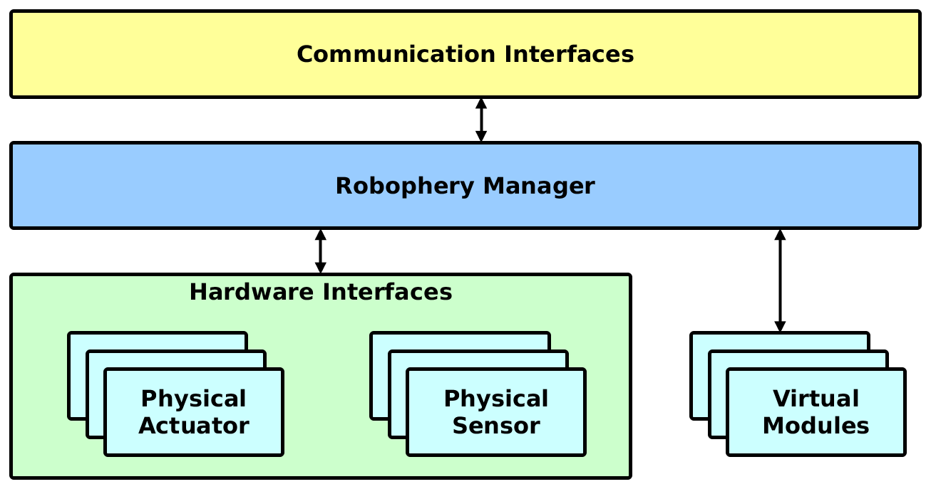
Autonomous Units
Autonomous unit is Python service, which communicates with hardware peripherals and sending and receiving data from external communication sources. RoboPhery unit consists of several objects. Communication objects handle sending and receiving messages from the upper layer services or other autonomous units. Interface objects handle abstraction to hardware communication at device level. Modules encapsulate individual hardware sensors and actuators. Finally the robophery manager serves as central service that connects all other models within the autonomous unit.
When data are collected from sensors, it is important to data will be transfered and stored in correct state to the highest part of system, e.g. to time-series database.
Message Bus mainly take care about communication between agent in Autonomous Agent System, because data can’t be easily transfered from sensor (agent) to database directly. Message Bus also can aggregate data to bigger units or make some basic transformations.
Autonomous services take care about conditions from sensors and values, which are captured. There are predefined conditions and when captured values are identical with same condition, monitoring agent send a message via message bus to reacting agent, which will performs predefined action.
Sample Devices
Following Figures shows simple device configurations.
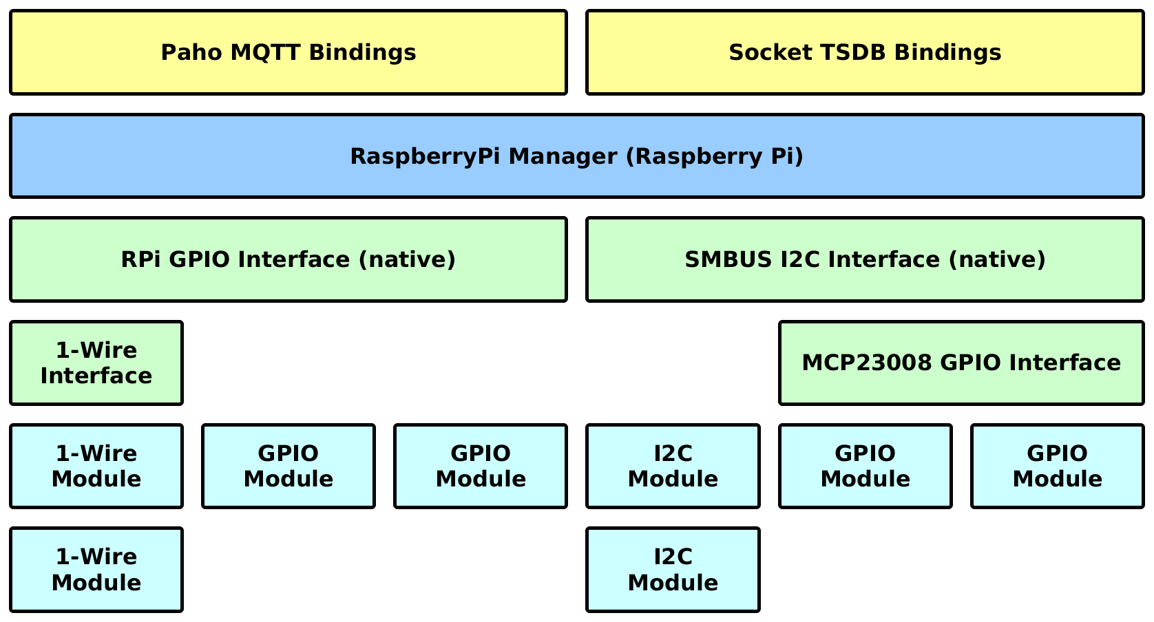
Raspberry Pi Device
Following figure shows RoboPhery service running on the Raspberry Pi device with MCP23008 I2C to GPIO expander and multiple sensors connected to individual interfaces.
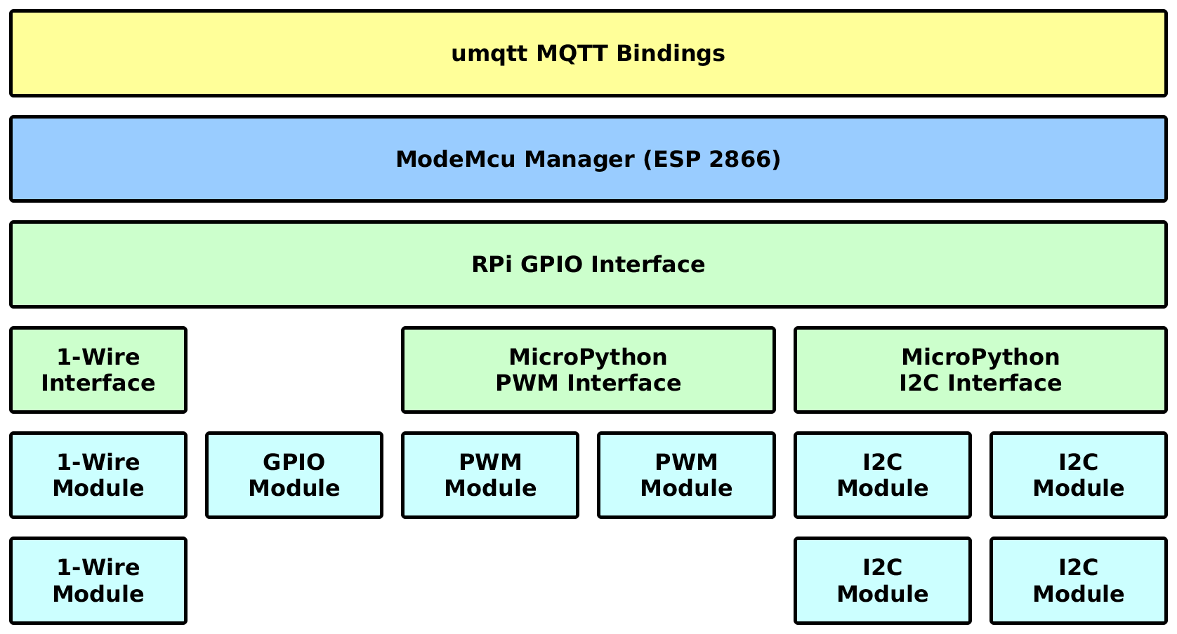
ModeMCU Device
Following figure shows RoboPhery service running on the Mode MCU device with multiple sensors connected to interfaces present on the device.
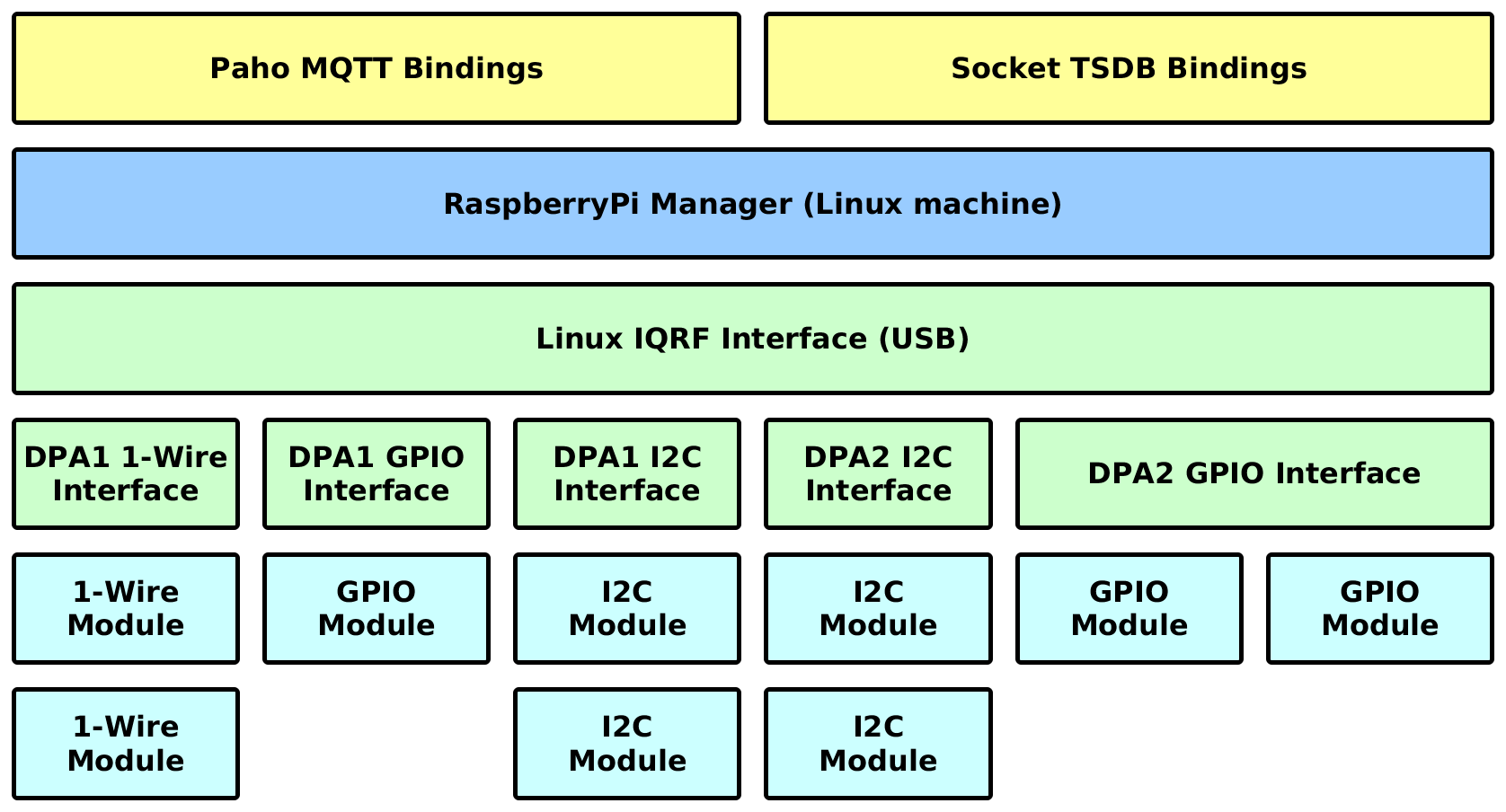
IQRF Platform
Following figure shows RoboPhery service running on the Raspberry Pi device with IQRF coordinator with sensor interfacess connected through a mesh network and IQRF interface.
Physical Modules
Interfaces
Following categories show available sensor and actuator types supported by the RoboPhery platform.
Physical Modules
Physical Sensors
- Air Humidity - Ratio of water vapor pressure to the equilibrium vapor pressure of water
- Air Pressure The force per unit area exerted on a surface by the weight of air above that surface in the atmosphere of Earth
- Distance - The distance from the observer to a target
- Electric Circuit - Measuring connecting or disconnecting electric circuit (buttons, PIR sensors, floats)
- Electric Consumption - The amount of electric energy consumed by any electrically powered device
- Revolution Count - Revolutions counter per given time (fans, flow meters)
- Luminosity of Light - A measure of the intensity of light that hits a surface
- Color of Light
- Liquid Flow - Quantification of bulk fluid movement
- Liquid Level - The level of liquid in a container
- Liquid pH - Acidity or basicity of an aqueous solution
- Reduction Potential of Liquid - A measure of the tendency of a chemical species to acquire electrons and thereby be reduced
- Oxygen Saturation of Liquid
- Electric Conductivity of Liquid
- Soil Moisture - The water content in soil
- Temperature - A comparative objective measure of hot and cold
Physical Actuators
Virtual Modules
Virtual devices represent module aggregation and are useful when encapsulating some higher logic (lean right at 6 legged spider) or make autonomous computation when communication layer goes down.
External Resources
Following resources were useful while creating this project.
Hardware Driver Libraries
Multiple sensors at consistent libraries
- http://iotdk.intel.com/docs/master/upm/python/modules.html (Intel IoT Development Kit)
- https://github.com/ControlEverythingCommunity/CE_PYTHON_LIB (Control Everything modules)
- https://github.com/8devices/IoTPy (8Devices modules)
- https://github.com/sensorian/sensorian-firmware/tree/master/Drivers_Python (Sensorian Python Library)
Chapter 2. Installation
Supported installation procedures.
Manual Installation
RoboPhery is simple Python application suitable to run with minimal resources and dependencies.
Installation
Virtualenv
Install required dependencies
apt-get install python-dev libyaml-dev git python-virtualenv
Prepare clean virtualenv
virtualenv /opt/robophery
Clone this repository
git clone https://github.com/cznewt/robophery.git
Install dependencies and robophery
source /opt/robophery/bin/activate
pip install -r requirements.txt
python setup.py install
Service
If you are running systemd-enabled distribution, setup systemd unit file to start robophery automatically:
cat << EOF >>/etc/systemd/system/robophery-manager.service
[Unit]
Description=robophery manager
Wants=mosquitto.service
After=network.target mosquitto.service

[Service]
Type=simple
User=root
Group=root
WorkingDirectory=/opt/robophery
Environment=ROBOPHERY_CONF=/etc/robophery
ExecStart=/opt/robophery/bin/rp_manager
RestartSec=5
Restart=on-failure

[Install]
WantedBy=multi-user.target
EOF
Create /opt/robophery directory and config file
/opt/robophery/robophery_conf.py and start the service.
systemctl daemon-reload
systemctl start robophery-manager
systemctl enable robophery-manager
To check status of a service, use systemctl status -l robophery-manager.
To see logs, you can use systemd journal (eg. journalctl -u robophery-manager -f)
Configuration
Following example configuration will setup robophery running on Raspberry Pi and will collect data from DHT22 sensor attached to GPIO pin 3 and publish it to MQTT every 60 seconds.
CONF = {
  'name': 'mylittleraspberry',
  'log_level': 'debug',
  'log_handlers': ['console', 'syslog'],
  'read_interval': 10000,
  'publish_interval': 60000,
  'platform': 'raspberrypi',
  'config': {
    'comm': {
      'default_mqtt': {
        'host': 'mymqttserver',
        'port': 1883,
        'class': 'robophery.comm.linux.mqtt.PahoMqttComm'
      },
    },
    'interface': {
      'local_gpio': {
        'engine': 'gpio',
        'class': 'robophery.platform.rpi.gpio.RaspberryPiGpioInterface'
      }
    },
    'module': {
      'dht22': {
        'data': {
          'pin': 3,
        },
        'class': 'robophery.module.gpio.dht22.Dht22Module'
      }
    }
  }
}
Salt installation
You can use salt-formula-robophery to automate both installation and configuration.
Following configuration sets up multiple sensors over multiple interfaces.
robophery:
  server:
    name: garden
    platform: raspberrypi
    log_level: debug
    log_handlers:
    - console
    read_interval: 3000
    publish_interval: 6000
    interface:
      local_gpio:
        class: robophery.platform.rpi.gpio.RaspberryPiGpioInterface
        engine: gpio
      local_i2c:
        class: robophery.platform.linux.i2c.SMBusI2cInterface
        engine: i2c
        bus_number: 1
      local_w1:
        class: robophery.platform.linux.w1.LinuxW1Interface
        engine: w1
        data:
          iface: local_gpio
          pin: 4
    module:
      air_temp_humid:
        class: robophery.module.i2c.sht3x.Sht3xModule
        data:
          addr: 0x44
          iface: local_i2c
      light_luminosity:
        class: robophery.module.i2c.bh1750.Bh1750Module
        data:
          addr: 0x23
          iface: local_i2c
      light_switch:
        class: robophery.module.gpio.relay.RelayModule
        invert_logic: true
        data:
          iface: local_gpio
          pin: 36
      air_fan_switch:
        class: robophery.module.gpio.relay.RelayModule
        invert_logic: true
        data:
          iface: local_gpio
          pin: 38
      nutrient_pump_switch:
        class: robophery.module.gpio.relay.RelayModule
        invert_logic: true
        data:
          iface: local_gpio
          pin: 40
      water_pump_switch:
        class: robophery.module.gpio.relay.RelayModule
        invert_logic: true
        data:
          iface: local_gpio
          pin: 12
      water_level:
        class: robophery.module.gpio.switch.SwitchModule
        data:
          iface: local_gpio
          pin: 13
          pull_up_down: down
      water_ph:
        class: robophery.module.i2c.ezoph.EzoPhModule
        data:
          addr: 0x68
          iface: local_i2c
      water_ec:
        class: robophery.module.i2c.ezoec.EzoEcModule
        data:
          addr: 0x69
          iface: local_i2c
      water_temp:
        class: robophery.module.w1.ds18.Ds18Module
        data:
          iface: local_w1
          addr: 00145071daff
        type: DS18B20
Chapter 3. Hardware Controllers
Target hardware devices for the RoboPhery platform.
Single-board Computers
A single-board computer (SBC) is a complete computer built on a single circuit board, with microprocessor(s), memory, input/output (I/O) and other features required of a functional computer. Single-board computers were made as demonstration or development systems, for educational systems, or for use as embedded computer controllers. Many types of home computers or portable computers integrate all their functions onto a single printed circuit board.
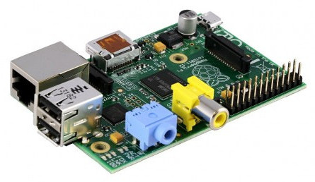
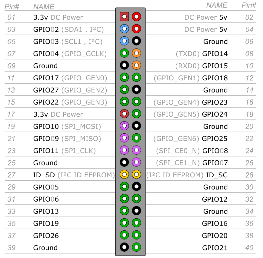
Raspberry Pi
The Raspberry Pi is a series of credit card-sized single-board computers developed in the UK by the Raspberry Pi Foundation with the intention of promoting the teaching of basic computer science in schools.
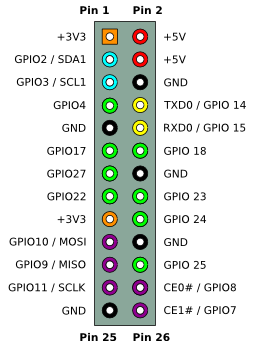
Available pins
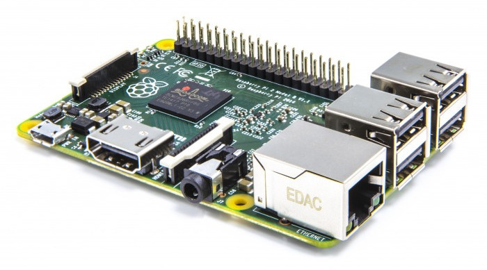
Raspberry Pi 2/3
The Raspberry Pi is a series of credit card-sized single-board computers developed in the UK by the Raspberry Pi Foundation with the intention of promoting the teaching of basic computer science in schools.
Available pins
More infromation
- Install Archlinux: http://archlinuxarm.org/platforms/armv7/broadcom/raspberry-pi-2
Where to buy
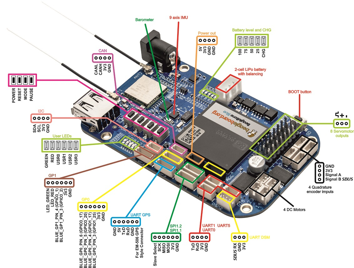
BeagleBone Black
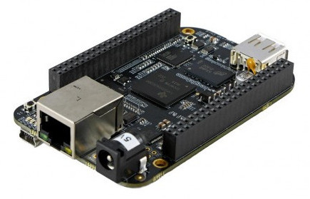
Available pins
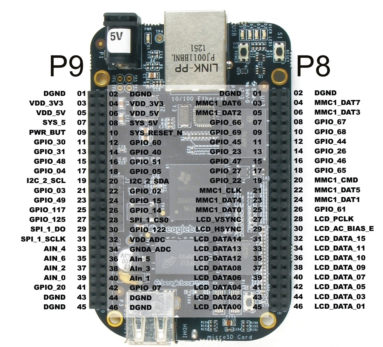
- 7 Analog Pins
- 65 Digital Pins at 3.3V
- 2x I2C
- 2x SPI
- 2x CAN Bus
- 4 Timers
- 4x UART
- 8x PWM
- A/D Converter
More infromation
- Install Archlinux: http://archlinuxarm.org/platforms/armv7/ti/beaglebone-black
- Install Raspbian: http://www.raspberrypi.org/documentation/installation/installing-images/linux.md
- Install Ubuntu: http://www.armhf.com/boards/beaglebone-black/#trusty
Where to buy
- 1200 CZK - http://cz.farnell.com/element14/bbone-black-4g/beaglebone-black-rev-c-cortex/dp/2422228 - BeagleBone Black REV C
Single-board Microcontrollers
A single-board microcontroller is a microcontroller built onto a single printed circuit board. This board provides all of the circuitry necessary for a useful control task: a microprocessor, I/O circuits, a clock generator, RAM, stored program memory and any necessary support ICs. The intention is that the board is immediately useful to an application developer, without requiring them to spend time and effort to develop controller hardware.
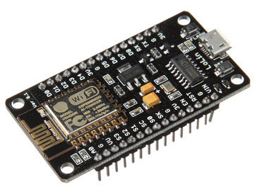
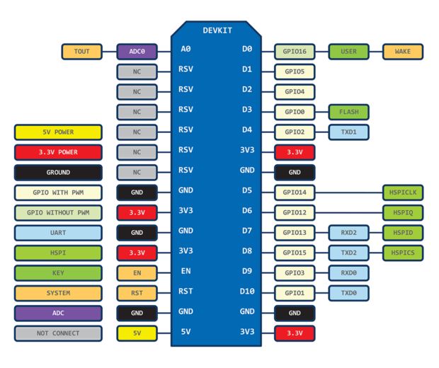
ESP8266 (NodeMCU)
The ESP8266 is a low-cost Wi-Fi chip with full TCP/IP stack and MCU (microcontroller unit) capability produced by Shanghai-based Chinese manufacturer, Espressif Systems.
The chip first came to the attention of western makers in August 2014 with the ESP-01 module, made by a third-party manufacturer, AI-Thinker. This small module allows microcontrollers to connect to a Wi-Fi network and make simple TCP/IP connections using Hayes-style commands. However, at the time there was almost no English-language documentation on the chip and the commands it accepted. The very low price and the fact that there were very few external components on the module which suggested that it could eventually be very inexpensive in volume, attracted many hackers to explore the module, chip, and the software on it, as well as to translate the Chinese documentation.
The ESP8285 is an ESP8266 with 1 MiB of built-in flash, allowing for single- chip devices capable of connecting to Wi-Fi.
NodeMCU is an open source IoT platform. It includes firmware which runs on the ESP8266 Wi-Fi SoC from Espressif Systems, and hardware which is based on the ESP-12 module.
Available pins
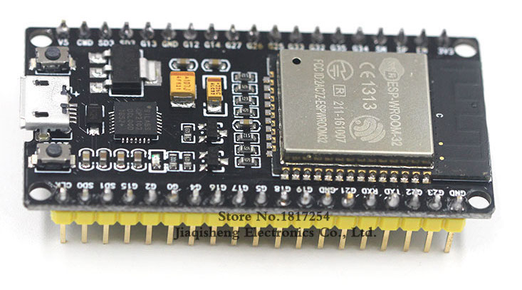
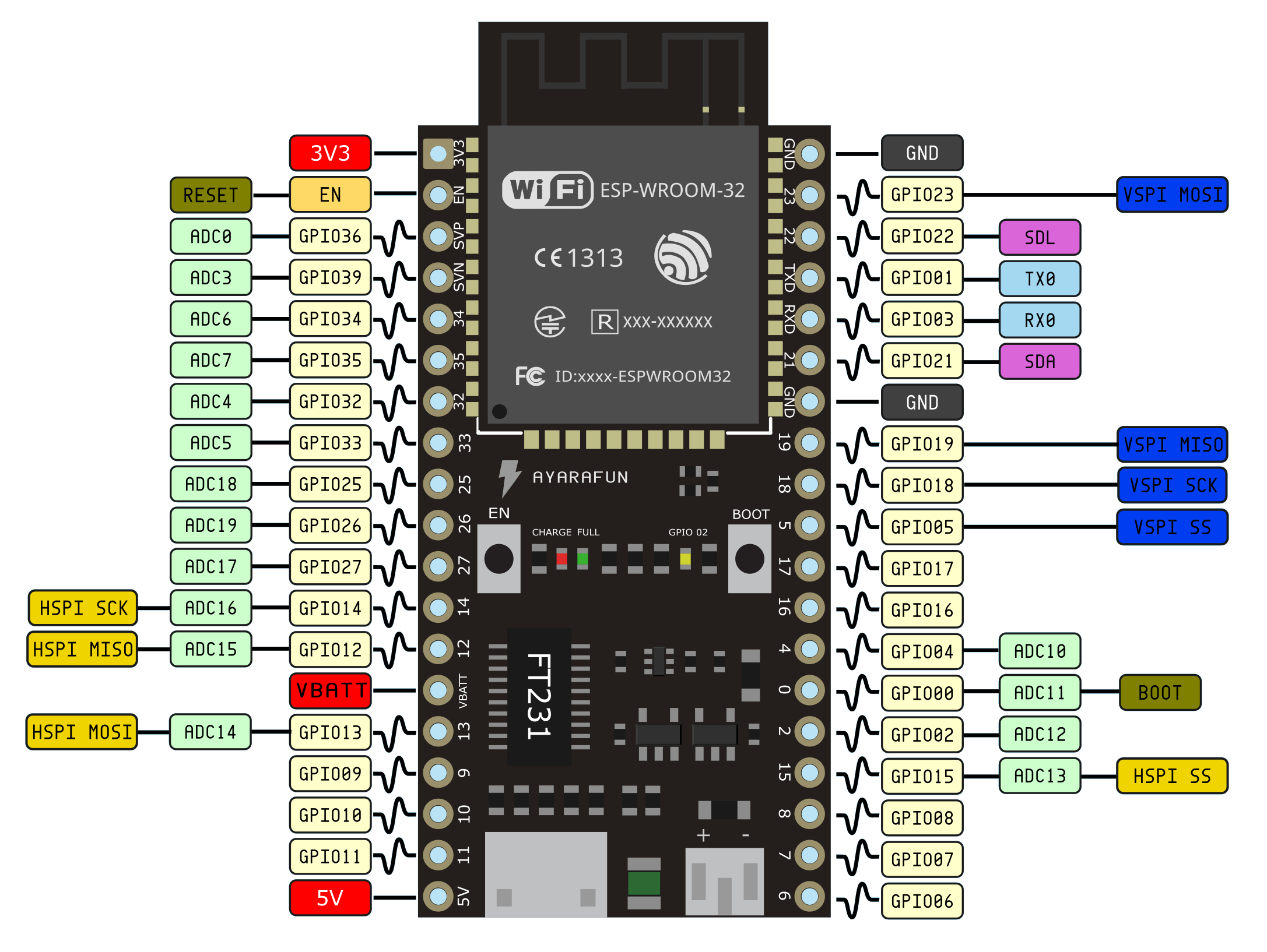
ESP32
ESP32 is a series of low cost, low power system on a chip microcontrollers with integrated Wi-Fi & dual-mode Bluetooth. The ESP32 series employs a Tensilica Xtensa LX6 microprocessor in both dual-core and single-core variations. ESP32 is created and developed by Espressif Systems, a Shanghai- based Chinese company, and is manufactured by TSMC using their 40 nm process. It is a successor to the ESP8266 microcontroller.
SP32 can perform as a complete standalone system or as a slave device to a host MCU, reducing communication stack overhead on the main application processor. ESP32 can interface with other systems to provide Wi-Fi and Bluetooth functionality through the SPI / SDIO or I2C / UART interfaces.
Available pins
More information
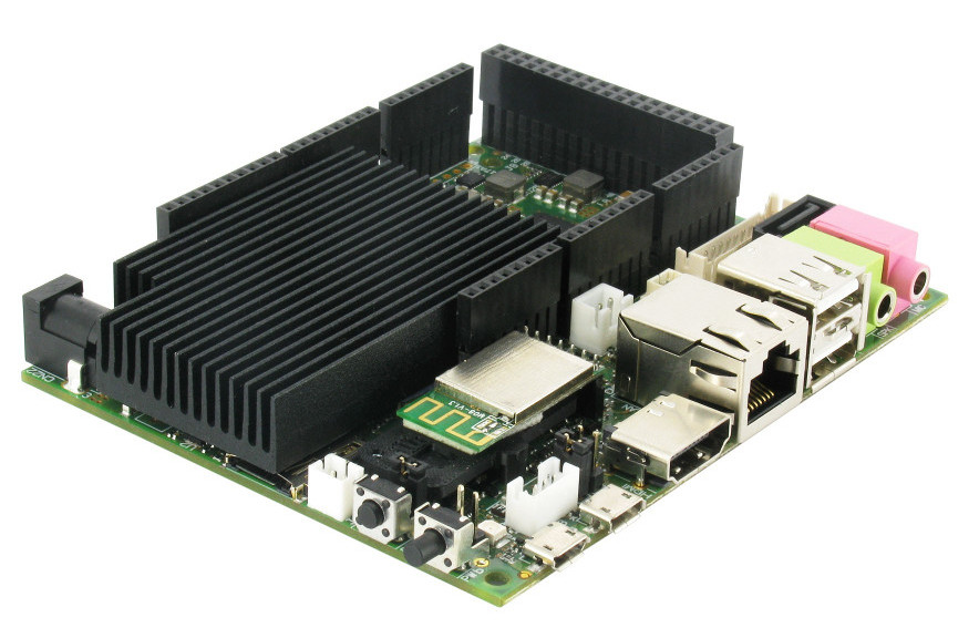
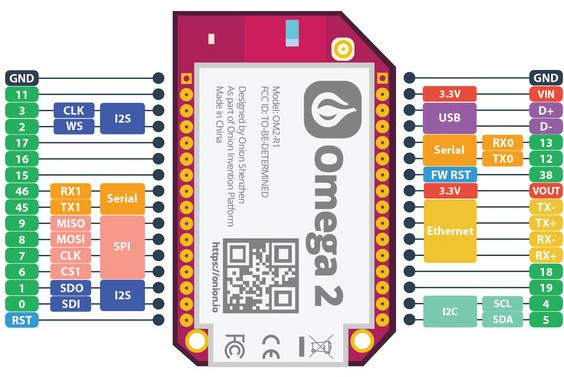
Onion Omega2
Omega2 is a personal single-board computer created by a startup company called Onion, released on Kickstarter. It is advertised as “the world’s smallest Linux Server” The system combines the tiny form factor and power- efficiency of the Arduino, with the power and flexibilities of the Raspberry Pi and is identified with FCC Identifier 2AJVP-OMEGA2. It runs Linux kernel based lightweight operating system for embedded system called OpenWRT.
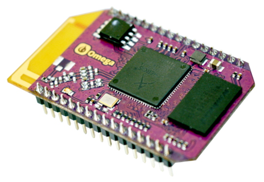
Available pins
More information
USB Extension Boards
Get additional GPOIO/I²C/SPI/AIN interfaces by USB port.
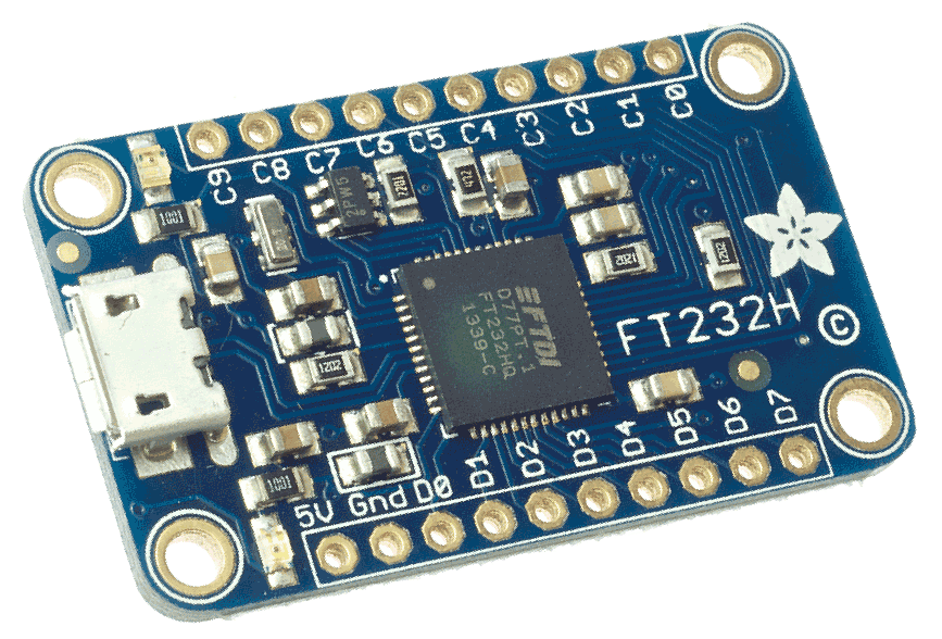
FT232H - USB to GPIO/SPI/I²C Extension Board
This chip from FTDI is similar to their USB to serial converter chips but adds a ‘multi-protocol synchronous serial engine’ which allows it to speak many common protocols like SPI, I²C, serial UART, JTAG, and more! There’s even a handful of digital GPIO pins that you can read and write to do things like flash LEDs, read switches or buttons, and more.
More information
- Adafruit FT232H Breakout https://learn.adafruit.com/adafruit-ft232h-breakout?view=all
- Official FT232H Datasheet http://www.adafruit.com/product/2264
- Adafruit FT232H With SPI & I2C Devices https://learn.adafruit.com/adafruit-ft232h-with-spi-and-i2c-libraries?view=all
- http://pandatron.cz/?2604&predstaveni_obvodu_ft232h
Where to buy
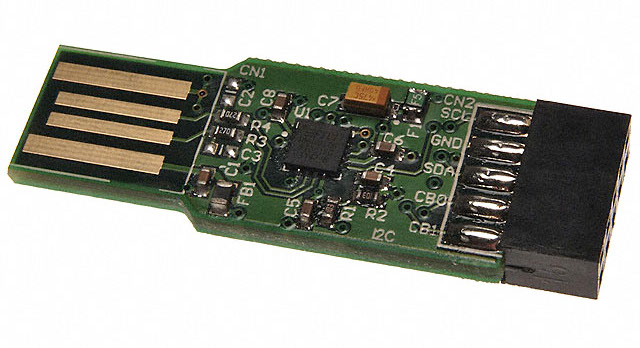
UMFT201XB - USB to GPIO/SPI/I²C Extension Board
The UMFT201XB bridges from USB to I²C two-wire serial bus interface. The UMFT220XB bridges from USB to Parallel 4-Bit FT1248 Interface. The UMFT230XB bridges from USB to Basic UART (Universal Asynchronous Receiver/Transmitter). The breakout board converts USB 2.0 Full-Speed to a serial interface. Serial signals on a 2.54mm (0.1) pitch 10-pin female connector.
The module plug directly into the USB host connector and the pads of the PCB makes electrical contact with the electrical contacts of the USB connector. The serial interface operate at +3.3V. Input/Output pins are 5V tolerant.
More information
- English Datasheet - http://pdf1.alldatasheet.com/datasheet-pdf/view/602893/ETC2/UMFT201XB.html
Where to buy
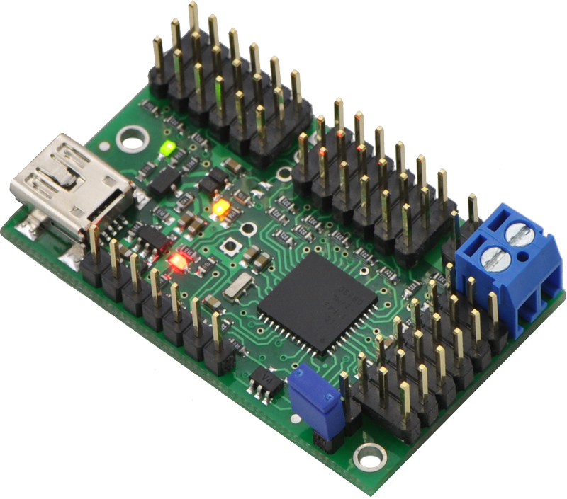
Maestro - USB to PWM Extension Board
The 18-channel Mini Maestro 18 raises the performance bar for serial servo controllers with features such as a native USB interface and internal scripting control. Whether you want the best servo control available (0.25μs resolution with built-in speed and acceleration control and pulse rates up to 333 Hz) or a general I/O controller (e.g. to interface with a sensor or ESC via your USB port), this compact, versatile device will deliver. This fully-assembled version ships with header pins installed.
More information
Where to buy
- 40 USD - https://www.pololu.com/product/1354
I²C Extension Boards
MCP23008 - I²C to GPIO Extension Board
Add another 8 pins to your microcontroller using a MCP23008 port expander. The MCP23008 uses two I²C pins (these can be shared with other I²C devices), and in exchange gives you 8 general purpose pins. You can set each of 8 pins to be input, output, or input with a pullup. There’s even the ability to get an interrupt via an external pin when any of the inputs change so you don’t have to keep polling the chip.
Use this chip from 2.7-5.5V (good for any 3.3V or 5V setup), and you can sink/source up to 20mA from any of the I/O pins so this will work for LEDs and such. Team it up with a high-power MOSFET if you need more juice. DIP package means it will plug into any breadboard or perfboard.
You can set the I²C address by tying the ADDR0-2 pins to power or ground, for up to 8 unique addresses. That means 8 chips can share a single I²C bus - that’s 64 I/O pins,
Where to buy
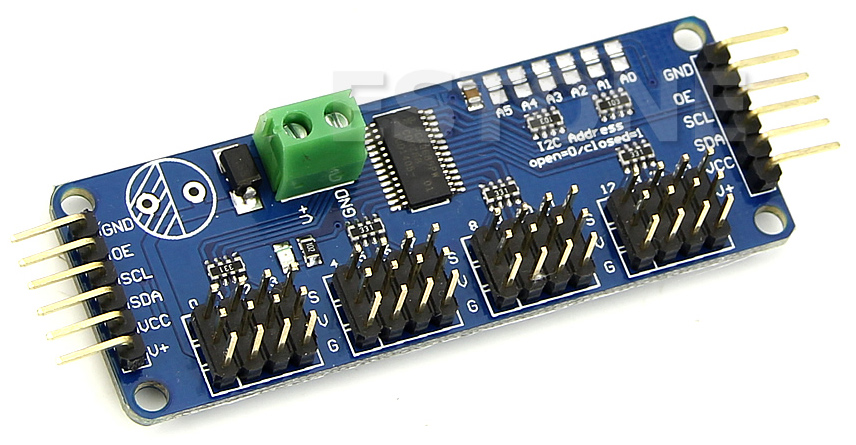
PCA9685 - I²C to PWM Extension Board
It’s an i2c-controlled PWM driver with a built in clock. That means that, unlike the TLC5940 family, you do not need to continuously send it signal tying up your microcontroller. It is 5V compliant, which means you can control it from a 3.3V microcontroller and still safely drive up to 6V outputs (this is good for when you want to control white or blue LEDs with 3.4+ forward voltages). 6 address select pins so you can wire up to 62 of these on a single i2c bus, a total of 992 outputs - that’s a lot of servos or LEDs.
Where to buy
- 15 USD - https://www.adafruit.com/product/815
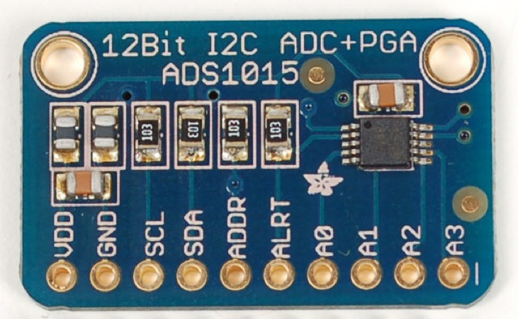
ADS1015 - I²C to ADC Extension Board
ADS1015 provides 12-bit precision at 3300 samples/second over I2C. The chip can be configured as 4 single-ended input channels, or two differential channels. As a nice bonus, it even includes a programmable gain amplifier, up to x16, to help boost up smaller single/differential signals to the full range.
More information
Where to buy
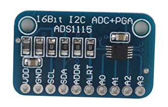
ADS1115 - I²C to ADC Extension Board
ADS1115 provides 16-bit precision at 860 samples/second over I2C. The chip can be configured as 4 single-ended input channels, or two differential channels. As a nice bonus, it even includes a programmable gain amplifier, up to x16, to help boost up smaller single/differential signals to the full range.
More information
Where to buy
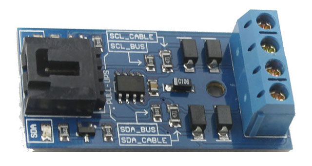
P82B715 - Active I²C Long Cable Extender
This module is designed to enable long range I2C communications which extends the cable length from several meters to about 50 meters. Operating with any I2C master, slave or bus buffer is the primary advantage of this module. NXP P82B715 I2C bus extender IC is used as the main component on this module. The module has four pull-up resistors on board: two on the unbuffered bus side and another two on the buffered bus side. Additionally, there are two LEDs indicates the SCL and SDA activities on the bus. Both the LEDs are driven by transistors which draw negligibly small current from the SCL and SDA lines.
More information
Where to buy
Chapter 4. Hardware Interfaces
Supported interfaces of RoboPhery platform.
Wired Interfaces
GPIO
General-purpose input/output (GPIO) is a generic pin on an integrated circuit or computer board whose behavior—including whether it is an input or output pin—is controllable by the user at run time.
GPIO pins have no predefined purpose, and go unused by default. The idea is that sometimes a system integrator who is building a full system might need a handful of additional digital control lines—and having these available from a chip avoids having to arrange additional circuitry to provide them. For example, the Realtek ALC260 chips (audio codec) have 8 GPIO pins, which go unused by default. Some system integrators (Acer Inc. laptops) use the first GPIO (GPIO0) on the ALC260 to turn on the amplifier for the laptop’s internal speakers and external headphone jack.
More information
- White, Jon, ed. (2016). Raspberry Pi - The Complete Manual (7 ed.). Imagine Publishing. p. 36. ISBN 978-1785463709.
- https://en.wikipedia.org/wiki/General-purpose_input/output
- “General Purpose Input/Output”. Oracle® Java ME Embedded Developer’s Guide (8 ed.). Oracle Corporation. 2014.
I²C
I²C (Inter-Integrated Circuit), pronounced I-squared-C, is a multi-master, multi-slave, packet switched, single-ended, serial computer bus invented by Philips Semiconductor (now NXP Semiconductors). It is typically used for attaching lower-speed peripheral ICs to processors and microcontrollers in short-distance, intra-board communication. Alternatively I²C is spelled I2C (pronounced I-two-C) or IIC (pronounced I-I-C).
Since October 10, 2006, no licensing fees are required to implement the I²C protocol. However, fees are still required to obtain I²C slave addresses allocated by NXP.
Several competitors, such as Siemens AG (later Infineon Technologies AG, now Intel mobile communications), NEC, Texas Instruments, STMicroelectronics (formerly SGS-Thomson), Motorola (later Freescale, now merged with NXP), Nordic Semiconductor and Intersil, have introduced compatible I²C products to the market since the mid-1990s.
More information
- https://en.wikipedia.org/wiki/I%C2%B2C
- Official I2C Specification Version 6 - http://www.nxp.com/documents/user_manual/UM10204.pdf
Dallas 1-wire
The 1-Wire system is the invention of Dallas Semiconductors, who were acquired by Maxim in 2001. 1-Wire and iButton are essentially two implementations of the same technology, the former being manufactured in traditional IC packages and the latter in a robust stainless steel package (shaped in like a button). This section focuses on the 1-Wire devices and networks.
1-Wire is a bit of a misnomer, since the bus in fact requires two wires. One wire is a ground wire and the the second carries both power and data. Many 1-Wire sensors are inexpensive and bus-powered, using a small capacitor to accumulate charge while the bus is idle and then using this stored energy to communicate with the bus master when polled. More complex sensors require a regulated 5V supply or unregulated 12V, both of which can be supplied along with the serial bus through a single Cat-5 cable. The power is usually injected into each branch of the serial network by a hub.
Interference
If you have long 1-Wire network runs and are having problems with glitches you should add a Schottky diode to the end of your network. Typically a 1N5817 diode reverse biased across sensors will acheive this. Solder the side with the stripe to pin 2 and the other side to pin 1 of the DS18S20.
Usage
A 1-Wire network isn’t going to do everything but there are some things that it are particularly good at and for for which there is good support, with clever devices. Its inherent simplicity, low power consumption and fairly low speed, mean that it is well suited to basic monitoring situations and the main things I’m using it for are:
- Temperature sensors
- Door contact sensors
- Mains power present sensor
- Weather instruments
- Switching on/off devices/lighting
More information
- Maxim Dallas 1-Wire, MicroLan, iButton: A Hobbyist’s View http://www.arunet.co.uk/tkboyd/e1didx.htm
- Guidelines for Reliable Long Line 1-Wire Networks http://www.maximintegrated.com/en/app-notes/index.mvp/id/148
Powerline
Powerline technologies utilises the existing mains wiring in your home and use it to send communications messages. There are a few downsides with this technology. The first one is that it won’t work in the event of a power cut. The second one is that your mains power network has all sorts of devices plugged into it that generate interference and can reduce the reliability of communications sent over the mains power network. A third issue is that your mains network is electrically connected to that of you neighbours and if they are using similar equipment, this can also interfere with your system. Different powerline technologies can also often not co-exist happily in the same home.
Powerline Ethernet technology allows you to network devices using adaptors plugged into mains power sockets. Speeds of up to 200Mbps are currently available and newer standards will enable speeds up to 380Mbps.
Structured Wiring
Structured wiring is a concept where all wires and cabling run from one single point in your home, to enable communications, entertainment and home automation. Structured wiring is the network for all of these services and is where you would typically install your home automation system. The approach allows flexible use of the installed networking cables and simply reconfiguration to support new services and requirements.
One of the main benefits of structured wiring is its inherent network capability. The frequency which the wires are capable of transmitting is often referred to as the bandwidth. Category 3 (Cat-3) cable is rated up to 16MHz. Category 5 (Cat-5) cable is more common in the UK and is rated to 100MHz. In a new build Category 6 (Cat-6) wiring is now most likely to be used, as it supports Gigabit Ethernet and bandwidths of over 500Mhz. It is ideal for people who wish to install large or complex home automation systems and transmit high-definition video around their home.
If you are considering home automation in a new house build, the question is not whether you should install structured wiring but one of how much and of what quality. The higher the quality of the cabling you use, the more superior your system will be and the more future-proof it will be. You may not need all of the capabilities that advanced cables can provide right away, but they might be just what you want in 5 years time. Because it is very expensive to upgrade your system retrospectively, your best bet is to think about your the future today.
Cabling & Ducting
The biggest challenge when retro-fitting home automation technology to an existing home is in solving the connectivity issues. For this reason alone many people use wireless technologies but, taking the time to add ducting and cables will make things more reliable and provide better performance in the long run. In a new build it is essential that ducts are provided to run cables to all the necessary devices and sockets.
In existing homes, one approach to adding new, hidden wiring is to use a combined skirting and ducting solution.
KNX
KNX is a standardized (EN 50090, ISO/IEC 14543), OSI-based network communications protocol for intelligent buildings. KNX is the successor to, and convergence of, three previous standards: the European Home Systems Protocol (EHS), BatiBUS, and the European Installation Bus (EIB or Instabus). The KNX standard is administered by the KNX Association.
More information
X10
X10 is an international and open standard for communication between electronic devices used for home automation. It was pretty much the first such technology on the market and is thus widely available and at mass-market prices.
The existing household electrical wiring (mains sockets and lighting) is used to send digital data between X10 devices. The data is encoded onto a 120kHz carrier which is transmitted as bursts during the zero crossing points of the 50 or 60Hz alternating current waveform. One bit is transmitted at each zero crossing and the zero crossing is used to improve signal to noise ratios.
To allow the operation of wireless keypads, remote switches, etc., a radio protocol is also defined. This operates at a frequency of 310MHz in the U.S. and 433MHz in Europe. The wireless devices send data packets that are very similar to ordinary X10 power line control packets. A radio receiver provides a bridge which translates the radio packets into ordinary X10 power line control packets.
X10 is at the cheaper end of the market when it comes to home automation but, it does have its uses. It’s also not as reliable as some of the later and more expensive technologies. Aside from its price, it is fairly easy to retrospectively fit into your existing home. One of the downsides to this technology is the relatively low number of devices (16 per house, though you can use more than one house code) that you can install in a single home. Another disadvantage is that you cannot interogate the status of most X10 modules.
Wireless Interfaces
BlueTooth
Bluetooth uses the same 2.4Ghz unlicensed band as most Wi-Fi routers. Bluetooth Low Energy (BLE) is also known as Bluetooth 4.0 and Bluetooth Smart. It’s called low-energy because it basically is. BLE devices can run for more than 2 years with a single coin battery depending on the signal strenth and how frequently they broadcast information.
Apple iBeacon uses Bluetooth Low Energy to create ‘beacon’ around regions so apps can be alerted when users enter them. The hardware beacons are a small wireless sensors placed inside any physical space that transmit data to your iPhone using Bluetooth Low Energy. iOS devices can also be iBeacons. Whilst Google have focussed on Near Field Communication (NFC), Android V4.3 has native support for Bluetooth Low Energy.
Z-Wave
Z-Wave is a widely adopted, proprietary standard for wireless home control and automation. It enables an affordable set of Z-Wave products, which interoperate with each other regardless of brand. Each Z-Wave certified product has to pass a stringent conformance tests to assure it meets the Z-Wave standard for operation and interoperability with other Z-Wave certified devices and controls.
Z-Wave enabled products offer reliable, confirmable, 2-way control communications throughout the home, without the need for any new wiring or any complex programming. It has been designed for residential and light commercial applications such as lighting control, thermostats, garage doors and access control, security systems, blinds and curtains, Internet gateways, PC applications, media centre integration, and universal remote controls.
The Z-Wave Alliance is a consortium of independent manufacturers who have agreed to build wireless home control products based on the Zensys Z-Wave standard.
Z-Wave uses mesh networking technology to route 2-way command signals from one Z-Wave device to another, around any obstacles or radio dead spots that might occur throughout the home. The result is assured, reliable whole-house coverage, with confirmation messages. As more devices are added, the mesh network becomes more robust. There is a limit to the number of devices that can form a single mesh network but it is over 200. European Z-Wave devices operate at 868.42MHz making them incompatible with their US equivalents operating at 908.42MHz
There is a lot of open source activity underway that uses Z-Wave. The Open Z-wave group have a goal to create free software to interface with all available Z-Wave PC controllers, allowing anyone to create applications that manipulate and respond to devices on a Z-Wave network, without requiring in- depth knowledge of the Z-Wave protocol or the purchase of expensive development kits.
ZigBee
ZigBee is more of a standard (802.15) than a brand name, which is why you won’t find much when searching for ‘Zigbee products’. There is an entire framework for development with the ZigBee Alliance, ZigBee PRO standard and ZigBee Home Automation application profile. The idea is that by making life simpler for product developers we will see a variety of competing brands offering every product the consumer could imagine. It has taken many years for the ZigBee concept to ratify itself into a standard.
One of the main companies using ZigBee technology is Control4, who sell a variety of lighting switches and controls. The main issue with their product set is that they are primarily sold through installers and not for a DIY solutions.
One of the key advantages of ZigBee is its very low power consumption, which made it ideal for battery operated devices and locations where wiring would be difficult. Another advantage is that ZigBee is an open standard, so in theory there is no dependency on a single manufacturer or supplier.
More information
Wi-Fi
IQRF
Chapter 5. Physical Actuators
Switching Electric Power
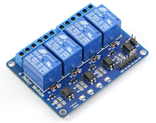
Generic PWM Switch - PWM Switch Actuator
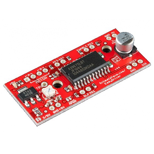
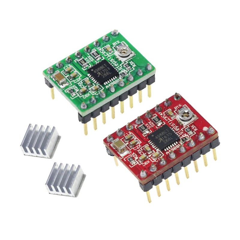
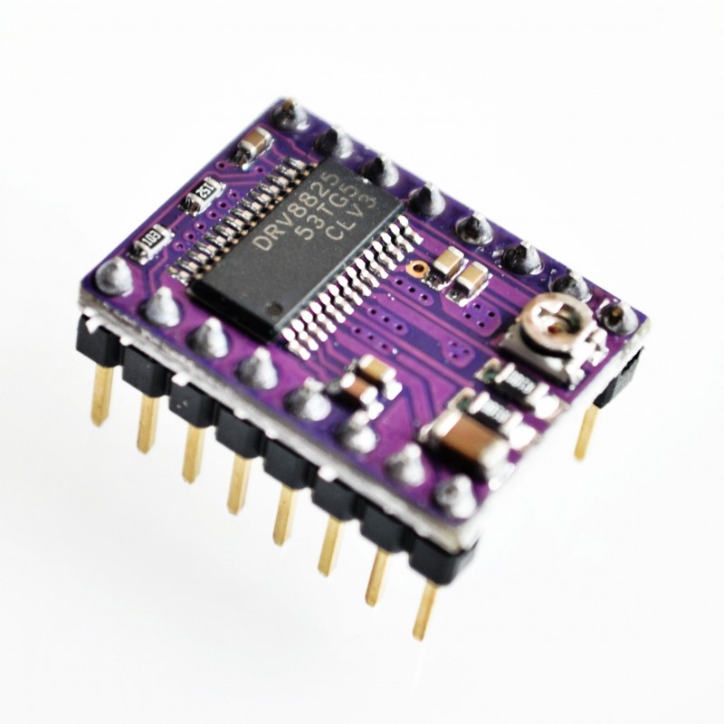
Controlling Electric Stepper Motor
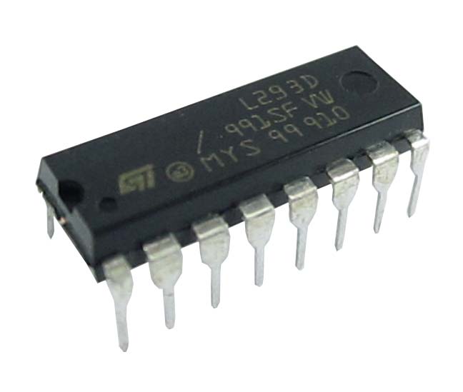
L293D - GPIO DC/Stepper Motor Actuator
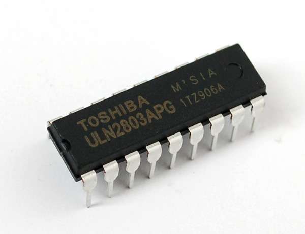
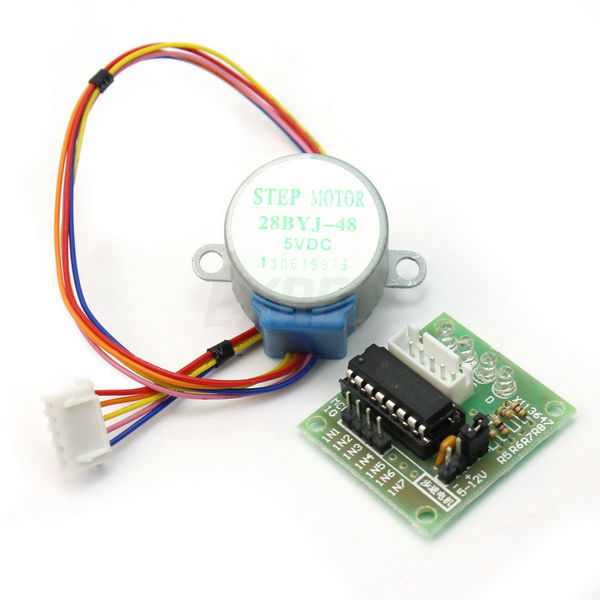
ULN2803 - GPIO DC/Stepper Motor Actuator
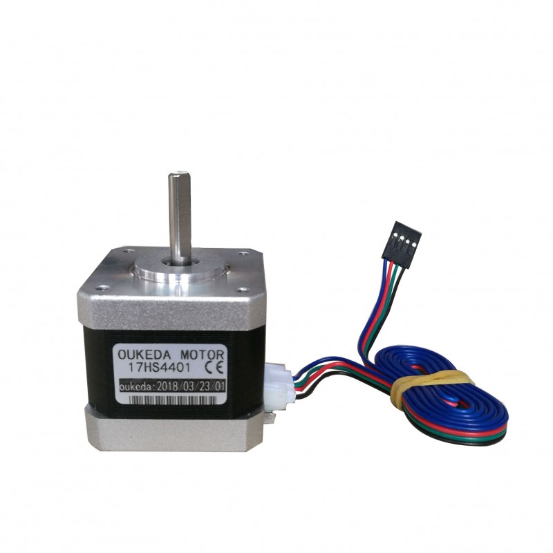
NEMA-17 - Stepper Motor
OLED Display
An organic light-emitting diode (OLED) is a light-emitting diode (LED) in which the emissive electroluminescent layer is a film of organic compound that emits light in response to an electric current. This layer of organic semiconductor is situated between two electrodes; typically, at least one of these electrodes is transparent. OLEDs are used to create digital displays in devices such as television screens, computer monitors, portable systems such as mobile phones, handheld game consoles and PDAs. A major area of research is the development of white OLED devices for use in solid-state lighting applications.
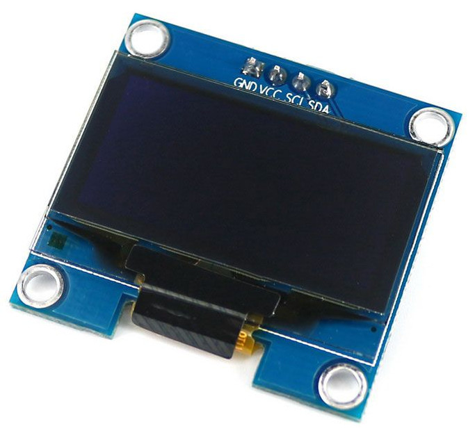
0,96” 128x64 - I²C OLED Display
These displays are small, only about 1” diagonal, but very readable due to the high contrast of an OLED display. This display is made of 128x32 individual white OLED pixels, each one is turned on or off by the controller chip. Because the display makes its own light, no backlight is required. This reduces the power required to run the OLED and is why the display has such high contrast. The driver chip SSD1306, communicates via I2C only.
More information
Where to buy
LCD Display
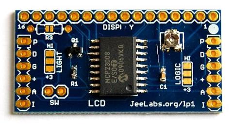
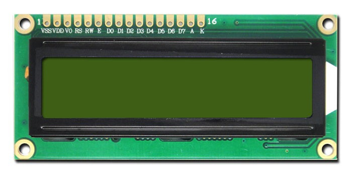
HD44780 - GPIO LCD Display
Standard HD44780 LCDs are useful for creating standalone projects. Comes in 16x2 or 20x4 sizes. Connection port is 0.1” pitch, single row for easy breadboarding and wiring. Pins are documented on the back of the LCD to assist in wiring it up. Single LED backlight included can be dimmed easily with a resistor or PWM and uses much less power than LCD with EL (electroluminescent) backlights.
More information
Where to buy
Chapter 6. Physical Sensors
Measuring Air Humidity
Relative humidity (abbreviated RH) is the ratio of the partial pressure of water vapor to the equilibrium vapor pressure of water at the same temperature. Relative humidity depends on temperature and the pressure of the system of interest.
The relative humidity of an air-water mixture is defined as the ratio of the partial pressure of water vapour (H2O) in the mixture to the saturated vapour pressure of water at a given temperature. Thus the relative humidity of air is a function of both water content and temperature.
- http://en.wikipedia.org/wiki/Relative_humidity
- https://www.kandrsmith.org/RJS/Misc/Hygrometers/calib_many.html
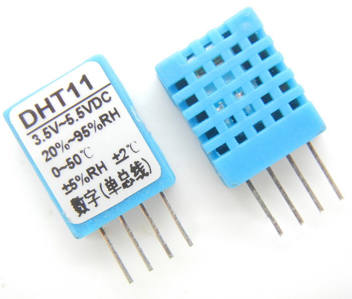
DHT11 - GPIO Humidity and Temperature Sensor
The DHT11 is a basic, ultra low-cost digital temperature and humidity sensor. It uses a capacitive humidity sensor and a thermistor to measure the surrounding air, and spits out a digital signal on the data pin (no analog input pins needed). Its fairly simple to use, but requires careful timing to grab data. The only real downside of this sensor is you can only get new data from it once every 2 seconds, so when using, sensor readings can be up to 2 seconds old.
More information
Where to buy
DHT22 - GPIO Humidity and Temperature Sensor
The DHT22 is a basic, low-cost digital temperature and humidity sensor. It uses a capacitive humidity sensor and a thermistor to measure the surrounding air, and spits out a digital signal on the data pin (no analog input pins needed). Compared to the DHT11, this sensor is more precise, more accurate and works in a bigger range of temperature/humidity, but its larger and more expensive.
More information
Where to buy
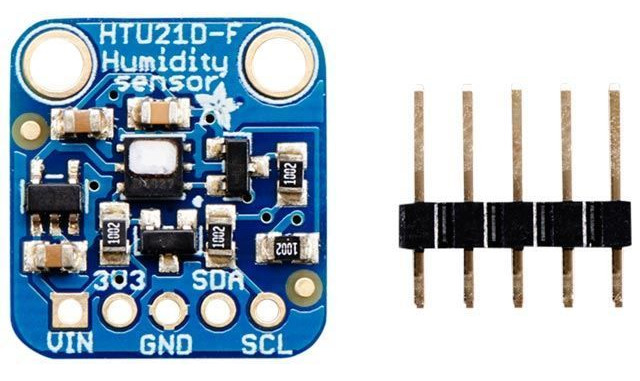
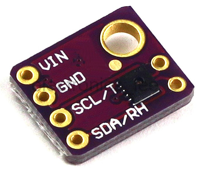
HTU21D - I²C Humidity and Temperature Sensor
This I²C digital humidity sensor is an accurate and intelligent alternative to the much simpler Humidity and Temperature Sensor - SHT15 Breakout It has a typical accuracy of ±2% with an operating range that’s optimized from 5% to 95% RH. Operation outside this range is still possible - just the accuracy might drop a bit. The temperature output has an accuracy of ±1°C from -30~90°C. If you’re looking to measure temperature more accurately, we recommend the MCP9808 High Accuracy I²C Temperature Sensor Breakout Board.
More information
- English datasheet http://www.adafruit.com/datasheets/1899_HTU21D.pdf
- http://randymxj.com/?p=550 - Python Library for HTU21D Humidity Sensor on Beaglebone Black and Raspberry Pi with Adafruit_I²C
- https://github.com/randymxj/Adafruit-Raspberry-Pi-Python-Code/tree/master/Adafruit_HTU21D - This library is used as source, requires Adafruit_I²C python library to work
- https://learn.adafruit.com/adafruit-htu21d-f-temperature-humidity-sensor?view=all
Where to buy
- 15 USD - http://www.adafruit.com/product/1899
- 15 USD - https://www.sparkfun.com/products/12064
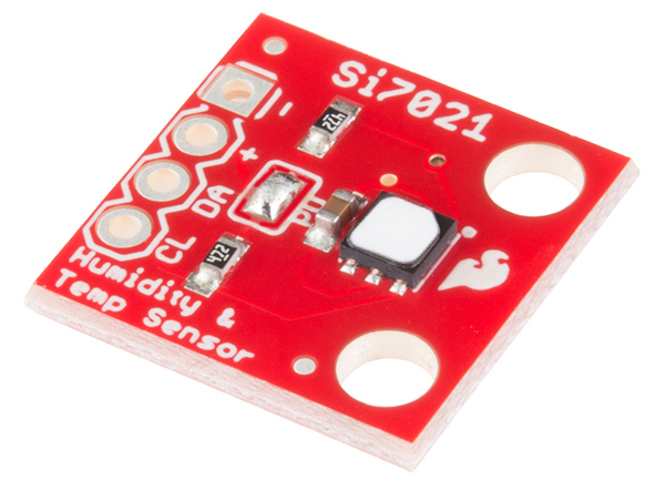
SI7021 - I²C Humidity and Temperature Sensor
The Si7021 is a low-cost, easy to use, highly accurate, digital temperature and humidity sensor. All you need is two lines for I2C communication, and you’ll have relative humidity readings and accurate temperature readings as well! This sensor is ideal for environmental sensing and data logging, perfect for a weather station or humidor control system.
More information
Where to buy
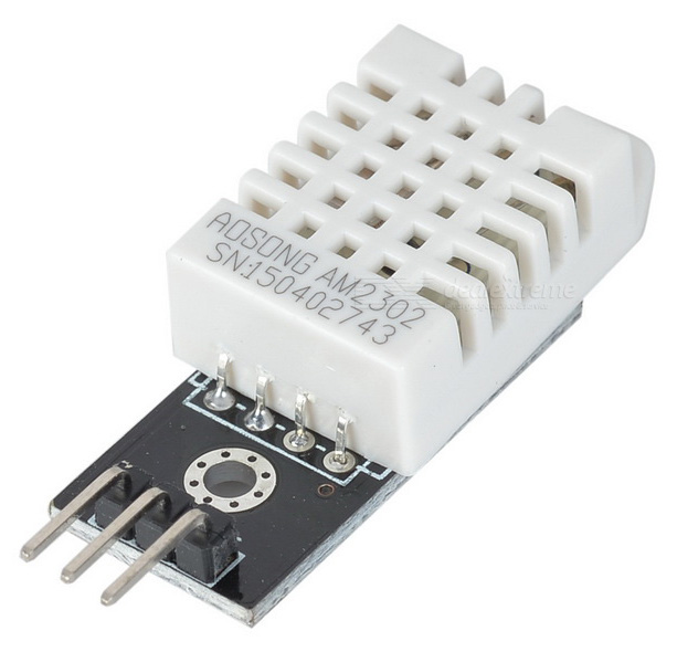
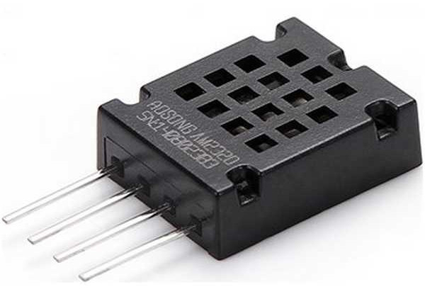
AM2320 - I²C Humidity and Temperature Sensor
The AM2320 is effectively the latest version of the AM2302 with the addition of an option to communicate over I2C interface. It is physically a little smaller, but with identical pin-out. The one-wire serial of the AM2302 is retained making this a simple drop-in replacement.
More information
SHT30/SHT31 - I²C Humidity and Temperature Sensor
Sensiron Temperature/Humidity sensors are some of the finest & highest- accuracy devices you can get. And, finally we have some that have a true I2C interface for easy reading.
More information
Where to buy
- 14 USD - https://www.adafruit.com/product/2857
- 5 USD - aliexpress
Measuring Air Pressure
Atmospheric pressure, sometimes also called barometric pressure, is the pressure within the atmosphere of Earth (or that of another planet). In most circumstances atmospheric pressure is closely approximated by the hydrostatic pressure caused by the weight of air above the measurement point. As elevation increases, there is less overlying atmospheric mass, so that atmospheric pressure decreases with increasing elevation. Pressure measures force per unit area, with SI units of pascals (1 Pa = 1 N/m2).
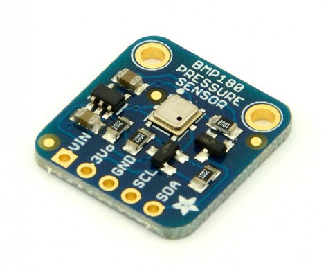
BMP085/180 - I²C Temperature and Pressure Sensor
BMP180 is a high accuracy, mini size, ultra-low power pressure sensor, can be used in mobile devices; Excellent performance, absolute accuracy minimum up to 0.03hPa, and ultra-low power consumption, only 3μA; BMP180 adopts 8-pin leadless ceramic chip carrier (LCC) super thin encapsulation; Directly connect to microprocessor via I²C highway; Main features: Pressure range: 300~1100hPa (altitude -500~9000 meters).
More information
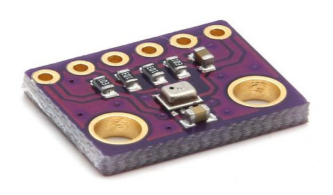
BMP280 - I²C Temperature and Pressure Sensor
Measuring Air Quality
Detecting particles within the air.
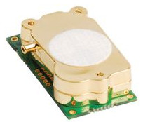
T6713 - I²C CO2 Concentration Sensor
The new T6700 series is a miniature NDIR CO2 sensor that has accuracy and reliability of many larger sensors. The new small size allows OEM’s to integrate in to smaller enclosures and equipment and uses significantly less power than many other devices on the market.
The Telaire T6713 CO2 Module is ideal for applications where accurate CO2 levels need to be measured and controlled for indoor air quality and energy saving applications such as demand control ventilation.
All units are factory calibrated to measure CO2 concentration levels up to 5000ppm, while maintaining accuracy across the range.
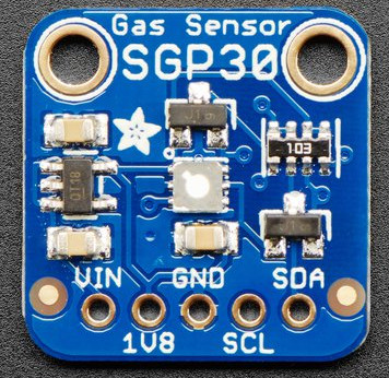
SGP30 - I²C CO2 Concentration and Volatile Organic Compound Sensor
This is a gas sensor that can detect a wide range of Volatile Organic Compounds (VOCs) and H2 and is intended for indoor air quality monitoring. When connected to your microcontroller (running our library code) it will return a Total Volatile Organic Compound (TVOC) reading and an equivalent carbon dioxide reading (eCO2) over I2C.
The SGP30 has a ‘standard’ hot-plate MOX sensor, as well as a small microcontroller that controls power to the plate, reads the analog voltage, tracks the baseline calibration, calculates TVOC and eCO2 values, and provides an I2C interface to read from. Unlike the CCS811, this sensor does not require I2C clock stretching.
More information
Where to buy
Measuring Distance
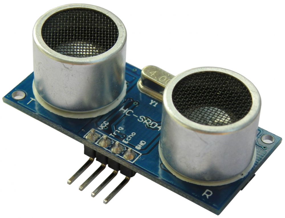
HC-SR04 - GPIO Ultasonic Distance Sensor
Ultrasonic ranging module HC - SR04 provides 2cm - 400cm non-contact measurement function, the ranging accuracy can reach to 3mm. The modules includes ultrasonic transmitters, receiver and control circuit.
More information
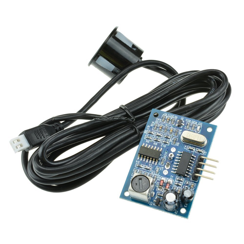
AJ-SR04M - GPIO Ultasonic Distance Sensor
AJ-SR04M Integration Ultrasonic Ranging Module Reversing Radar Waterproof Ultrasonic Square Wave TTL& Serial interface 20cm-8m.
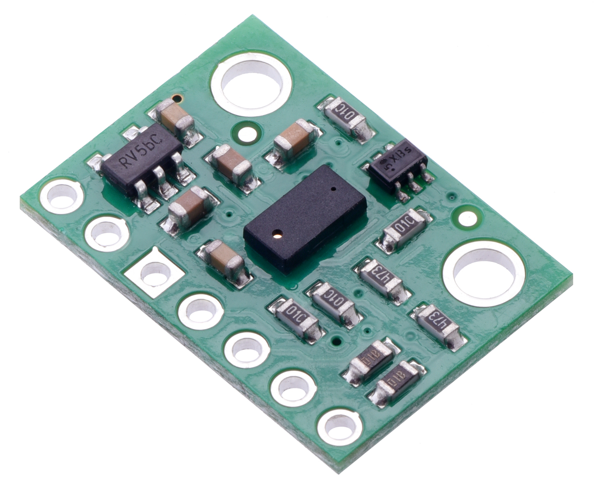
VL53l0X - I²C ToF Distance Sensor
The VL53L0X is a new generation Time-of-Flight (ToF) laser-ranging module housed in the smallest package on the market today, providing accurate distance measurement whatever the target reflectances unlike conventional technologies. It can measure absolute distances up to 2m, setting a new benchmark in ranging performance levels, opening the door to various new applications. The VL53L0X integrates a leading-edge SPAD array (Single Photon Avalanche Diodes) and embeds ST’s second generation FlightSenseTM patented technology.
The VL53L0X’s 940nm VCSEL emitter (Vertical Cavity Surface-Emitting Laser), is totally invisible to the human eye, coupled with internal physical infrared filters, it enables longer ranging distance, higher immunity to ambient light and better robustness to cover-glass optical cross-talk.
More information
Where to buy
- 14 USD - https://www.pololu.com/product/2490
Measuring Electric Current
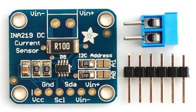
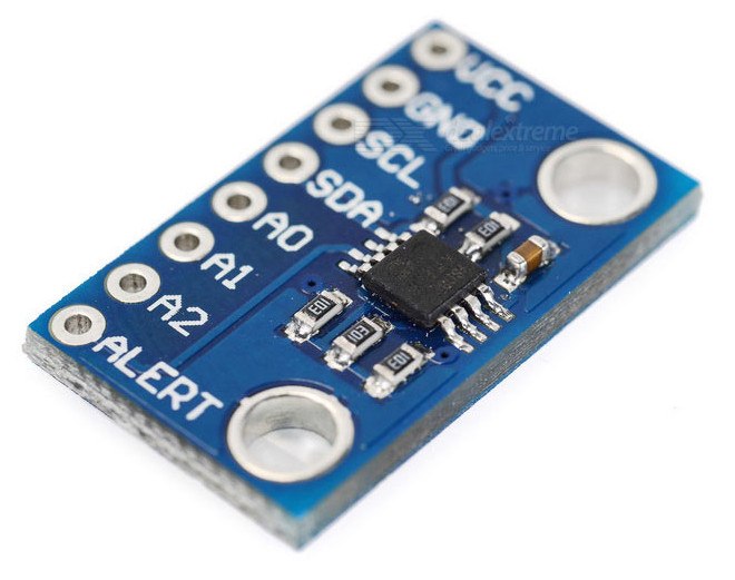
INA219 - I²C DC Current Sensor
Most current-measuring devices such as our current panel meter are only good for low side measuring. That means that unless you want to get a battery involved, you have to stick the measurement resistor between the target ground and true ground. This can cause problems with circuits since electronics tend to not like it when the ground references change and move with varying current draw. This chip is much smarter - it can handle high side current measuring, up to +26VDC, even though it is powered with 3 or 5V. It will also report back that high side voltage, which is great for tracking battery life or solar panels.
A precision amplifier measures the voltage across the 0.1 ohm, 1% sense resistor. Since the amplifier maximum input difference is ±320mV this means it can measure up to ±3.2 Amps. With the internal 12 bit ADC, the resolution at ±3.2A range is 0.8mA. With the internal gain set at the minimum of div8, the max current is ±400mA and the resolution is 0.1mA. Advanced hackers can remove the 0.1 ohm current sense resistor and replace it with their own to change the range (say a 0.01 ohm to measure up 32 Amps with a resolution of 8mA)
Where to buy
- 10 USD - https://www.adafruit.com/product/904
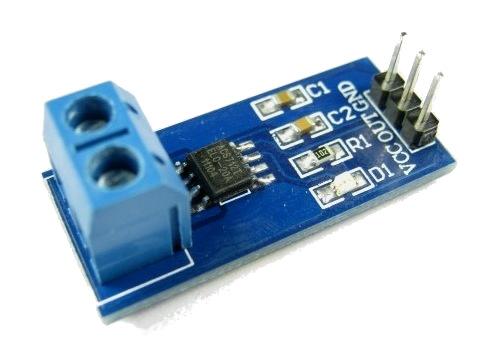
ACS712 - ADC Electrometer
Hall Effect based linear ACS712 current sensor. The sensor gives precise current measurement for both AC and DC signals. Thick copper conductor and signal traces allows for survival of the device up to 5 times overcurrent conditions.
The ACS712 outputs an analog voltage output signal that varies linearly with sensed current. The device requires 5VDC for VCC and a couple of filter capacitors. Please keep in mind that though the ACS712 is rated for 2.1kV isolation, the PCB it is on is not designed for that type of voltage. Please keep that in mind if you are using this breakout in high voltage applications.
More information
Where to buy
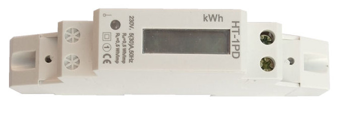
HT-1PD - GPIO Digital Electrometer
Jednofázový, jednosazbový podružný elektroměr pro montáž na DIN lištu. Impulsní výstup pro externí záznam spotřeby např. v PC (podle velikosti oakmžitého odběru se mění frekvence blikání LED diody a frekvence pulsů impulsního výstupu- viz. tech. parametry). Ideální pro měření spotřeby jednotlivých nájemníků, v autokempech, chatách apod.
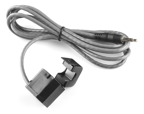
Non-Invasive Current Sensor
This non-invasive current sensor (also known as a “split core current transformer”) can be clamped around the supply line of an electrical load to tell you how much current is passing through it. It does this by acting as an inductor and responding to the magnetic field around a current-carrying conductor. By reading the amount of current being produced by the coil, you can calculate how much current is passing through the conductor.
This particular current sensor will measure a load up to 30 Amps which makes it great for building your own energy monitor to keep your power usage down, or even building an over-current protection device for an AC load. This sensor does not have a load resistor built in, so in most cases it will be necessary to place a resistor across the output to convert the coil’s induced current to a very small measurable voltage.
More information
Where to buy
Measuring Luminosity of Light
The lux is the SI unit of illuminance and luminous emittance, measuring luminous flux per unit area. It is equal to one lumen per square metre. In photometry, this is used as a measure of the intensity, as perceived by the human eye, of light that hits or passes through a surface. It is analogous to the radiometric unit watts per square metre, but with the power at each wavelength weighted according to the luminosity function, a standardized model of human visual brightness perception.
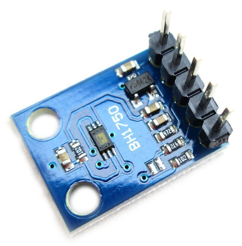
BH1750 - I²C Luminosity Sensor
Power supply: 3~5V; Data range: 0-65535; Sensor built-in and 16bitAD converter; Direct digital output, bypassing the complicated calculation, omit calibration; Do not distinguish between ambient light; Close to the visual sensitivity of spectral characteristics; For a wide range of brightness for 1 lux high precision measurement.
More information
Where to buy
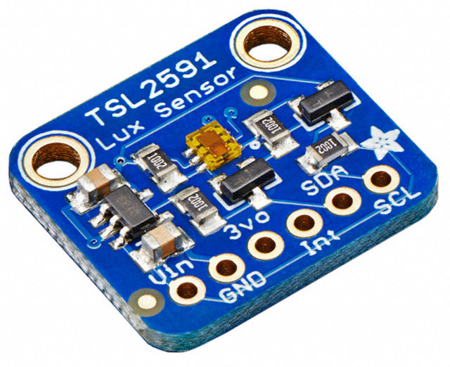
TSL2591 - I²C Luminosity Sensor
The TSL2591 luminosity sensor is an advanced digital light sensor, ideal for use in a wide range of light situations. Compared to low cost CdS cells, this sensor is more precise, allowing for exact lux calculations and can be configured for different gain/timing ranges to detect light ranges from 188 uLux up to 88,000 Lux on the fly.
The best part of this sensor is that it contains both infrared and full spectrum diodes! That means you can separately measure infrared, full-spectrum or human-visible light. Most sensors can only detect one or the other, which does not accurately represent what human eyes see (since we cannot perceive the IR light that is detected by most photo diodes) This sensor is much like the TSL2561 but with a wider range (and the interface code is different). This sensor has a massive 600,000,000:1 dynamic range! Unlike the TSL2561 you cannot change the I²C address, so keep that in mind. This board/chip uses I²C 7-bit address 0x29.
More information
Where to buy
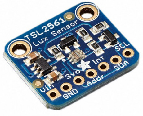
TSL2561 - I²C Luminosity Sensor
The TSL2561 luminosity sensor is an advanced digital light sensor, ideal for use in a wide range of light situations. Compared to low cost CdS cells, this sensor is more precise, allowing for exact lux calculations and can be configured for different gain/timing ranges to detect light ranges from up to 0.1 - 40,000+ Lux on the fly. The best part of this sensor is that it contains both infrared and full spectrum diodes! That means you can separately measure infrared, full-spectrum or human-visible light. Most sensors can only detect one or the other, which does not accurately represent what human eyes see (since we cannot perceive the IR light that is detected by most photo diodes)
The sensor has a digital (i2c) interface. You can select one of three addresses so you can have up to three sensors on one board - each with a different i2c address. The built in ADC means you can use this with any microcontroller, even if it doesn’t have analog inputs. The current draw is extremely low, so its great for low power data-logging systems. about 0.5mA when actively sensing, and less than 15 uA when in powerdown mode.
This board/chip uses I²C 7-bit addresses 0x39, 0x29, 0x49, selectable with jumpers.
Where to buy
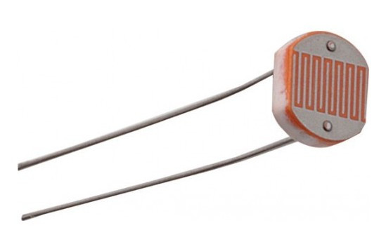
CdS - AIN Luminosity Sensor
CdS cells are little light sensors. As the squiggly face is exposed to more light, the resistance goes down. When its light, the resistance is about 5-10KΩ, when dark it goes up to 200KΩ.
To use, connect one side of the photo cell (either one, its symmetric) to power (for example 5V) and the other side to your microcontroller’s analog input pin. Then connect a 10K pull-down resistor from that analog pin to ground. The voltage on the pin will be 2.5V or higher when its light out and near ground when its dark.
More information
Where to buy
Measuring Color of Light
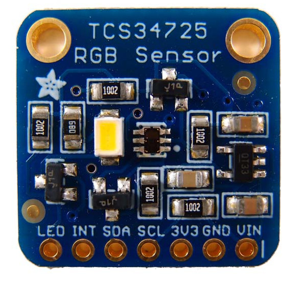
TCS34725 - I²C RGB Color Sensor
TCS34725 has RGB and Clear light sensing elements. An IR blocking filter, integrated on-chip and localized to the color sensing photodiodes, minimizes the IR spectral component of the incoming light and allows color measurements to be made accurately. The filter means you’ll get much truer color than most sensors, since humans don’t see IR. The sensor also has an incredible 3,800,000:1 dynamic range with adjustable integration time and gain so it is suited for use behind darkened glass.
You can power the breakout with 3-5VDC safely and level shifting for the I2C pins so they can be used with 3.3V or 5V logic. Neutral 4150°K temperature LED with a MOSFET driver onboard to illuminate what you’re trying to sense. The LED can be easily turned on or off by any logic level output.
Connect to any microcontroller with I2C and our example code will quickly get you going with 4 channel readings. We include some example code to detect light lux and temperature that we snagged from the eval board software.
More information
Where to buy
Measuring Flow of Liquid
Flow measurement is the quantification of bulk fluid movement. Flow can be measured in a variety of ways. Positive-displacement flow meters accumulate a fixed volume of fluid and then count the number of times the volume is filled to measure flow. Other flow measurement methods rely on forces produced by the flowing stream as it overcomes a known constriction, to indirectly calculate flow. Flow may be measured by measuring the velocity of fluid over a known area.
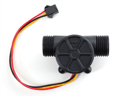
Plastic 1/2” - GPIO Liquid Flow Meter
Measure liquid/water flow for your solar, computer cooling, or gardening project using this handy basic flow meter. This sensor sit in line with your water line, and uses a pinwheel sensor to measure how much liquid has moved through it. The pinwheel has a little magnet attached, and there’s a hall effect magnetic sensor on the other side of the plastic tube that can measure how many spins the pinwheel has made through the plastic wall. This method allows the sensor to stay safe and dry.
The sensor comes with three wires: red (5-24VDC power), black (ground) and yellow (Hall effect pulse output). By counting the pulses from the output of the sensor, you can easily track fluid movement: each pulse is approximately 2.25 milliliters. Note this isn’t a precision sensor, and the pulse rate does vary a bit depending on the flow rate, fluid pressure and sensor orientation. It will need careful calibration if better than 10% precision is required. However, its great for basic measurement tasks!
Where to buy
- 10 USD - http://www.adafruit.com/products/828
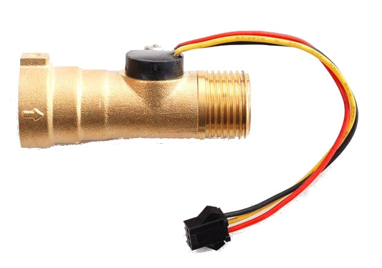
Brass 1/2” - GPIO Liquid Flow Meter
Measure liquid/water flow for your solar, computer cooling, or gardening project using this handy basic flow meter. This sensor sit in line with your water line, and uses a pinwheel sensor to measure how much liquid has moved through it. The pinwheel has a little magnet attached, and there’s a hall effect magnetic sensor on the other side of the plastic tube that can measure how many spins the pinwheel has made through the plastic wall. This method allows the sensor to stay safe and dry.
Where to buy
- 25 USD - http://www.adafruit.com/products/833
Measuring Liquid Level
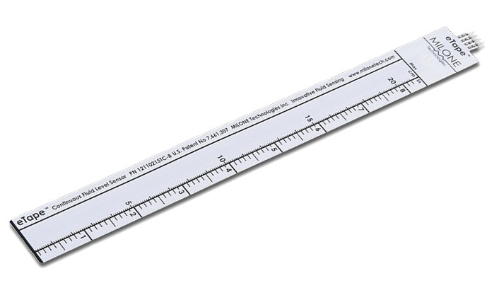
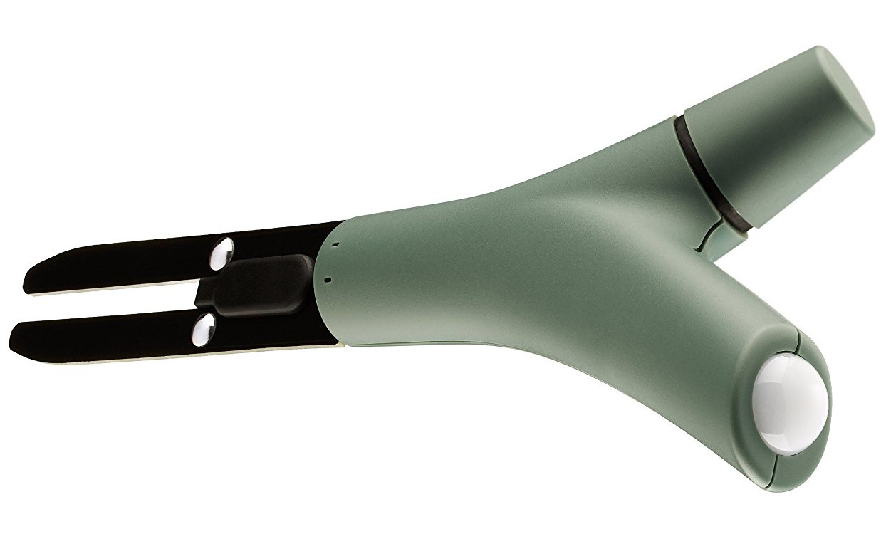
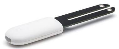
eTape Liquid Level Sensor
The eTape Liquid Level Sensor is a solid-state sensor with a resistive output that varies with the level of the fluid. It does away with clunky mechanical floats, and easily interfaces with electronic control systems. The eTape sensor’s envelope is compressed by the hydrostatic pressure of the fluid in which it is immersed. This results in a change in resistance that corresponds to the distance from the top of the sensor to the surface of the fluid. The sensor’s resistive output is inversely proportional to the height of the liquid: the lower the liquid level, the higher the output resistance; the higher the liquid level, the lower the output resistance.
This is a very unique sensor, we haven’t seen anything else that is affordable and accurate for measuring liquid level. This sensor seems like it would be a handy addition to an hydroponics, aquarium, fountain or pool controller, or perhaps measuring a rain tube.
More information
Where to buy
- 40 USD - 12” (320mm) http://www.adafruit.com/products/464
- 40 USD - 8” http://www.adafruit.com/products/463
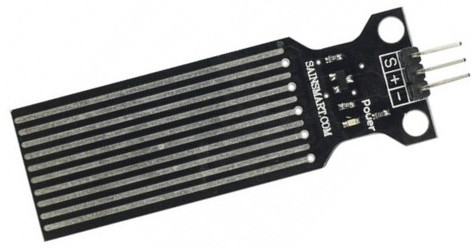
SainSmart Water Sensor
Water sensor brick is designed for water detection, which can be widely used in sensing the rainfall, water level, even the liquate leakage. The brick is mainly comprised of three parts: An Electronic brick connector, a 1 MΩ resistor, and several lines of bare conducting wires.
More information
Measuring Electric Conductivity of Liquid
In electrolytes, electrical conduction happens not by band electrons or holes, but by full atomic species (ions) traveling, each carrying an electrical charge. The resistivity of ionic solutions (electrolytes) varies tremendously with concentration – while distilled water is almost an insulator, salt water is a reasonable electrical conductor. Conduction in ionic liquids is also controlled by the movement of ions, but here we are talking about molten salts rather than solvated ions. In biological membranes, currents are carried by ionic salts. Small holes in cell membranes, called ion channels, are selective to specific ions and determine the membrane resistance.
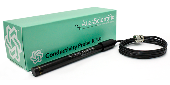
Atlas Scientific EC Kit - I²C Liquid Electric Conductivity Sensor
A conductivity probe is a very simple device. It is just two conductors with a fixed surface area at a fixed distance from each other. This distance and surface area is known as the conductivity cell. The cells distance and surface area is quantified as the conductivity cells K constant.
This Atlas Scientific conductivity probe, has a cell constant of K 1.0 When this conductivity probe is connected to an Atlas Scientific EZOTM conductivity circuit, it has a range of 5 µS/cm to 200,000 µS/cm.
More information
Where to buy
Measuring Oxygen Saturation of Liquid
Oxygen saturation (symbol SO2) is a relative measure of the amount of oxygen that is dissolved or carried in a given medium. It can be measured with a dissolved oxygen probe such as an oxygen sensor or an optode in liquid media, usually water. The standard unit of oxygen saturation is percent (%).
Dissolved oxygen is expressed in mg/L. There are many factors that must be taken into account when reading dissolved oxygen, such as salinity and temperature. Therefore, there is no simple linear equation that will derive the dissolved oxygen from the probes output voltage.
Atlas Scientific DO Kit - I²C Liquid Oxygen Saturation Sensor
This galvanic dissolved oxygen probe is a passive device that generates a small voltage from 0mv to 47mv depending on the oxygen saturation of the HDPE sensing membrane. This voltage can easily be read by a multimeter or an analog to digital converter.

Where to buy
Measuring pH of Liquid
pH is a measure of the acidity or basicity of an aqueous solution. Solutions with a pH less than 7 are said to be acidic and solutions with a pH greater than 7 are basic or alkaline. Pure water has a pH very close to 7.
- http://www2.ucy.ac.cy/~faniseng/publications/Sensors12.pdf - A Low-Cost System for Real Time Monitoring and Assessment of Potable Water Quality at Consumer Sites
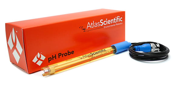
Atlas Scientific pH Kit - UART/I²C pH Sensor
The Atlas Scientific pH Kit comes with everything you need to get your laboratory grade embedded pH system up and running.
Remember, a pH Probe cannot be allowed to dry out or freeze. When it’s not in use keep it in the supplied soaker bottle. Periodically change out the storage solution in the soaker bottle with new storage solution.
More information
Where to buy
Measuring Oxidation/Reduction Potencial of Liquid
Reduction potential (also known as redox potential, oxidation / reduction potential, ORP, pE) is a measure of the tendency of a chemical species to acquire electrons and thereby be reduced. Reduction potential is measured in volts (V), or millivolts (mV). Each species has its own intrinsic reduction potential; the more positive the potential, the greater the species’ affinity for electrons and tendency to be reduced. ORP is a common measurement for water quality.
Atlas Scientific ORP Kit - I²C Liquid ORP Sensor
The Atlas Scientific ORP Kit comes with everything you need to get your laboratory grade embedded ORP system up and running.
Remember, a ORP Probe cannot be allowed to dry out or freeze. When it’s not in use keep it in the supplied soaker bottle. Periodically change out the storage solution in the soaker bottle with new storage solution.

More information
Where to buy
Measuring Position
More information
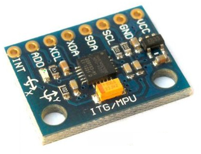
MPU6050 - I²C 3 Axis Accelerometer and Gyroscope
By combining a MEMS 3-axis gyroscope and a 3-axis accelerometer on the same silicon die together with an onboard Digital Motion Processor™ (DMP™) capable of processing complex 9-axis MotionFusion algorithms, the MPU-6050 does away with the cross-axis alignment problems that can creep up on discrete parts.
More information
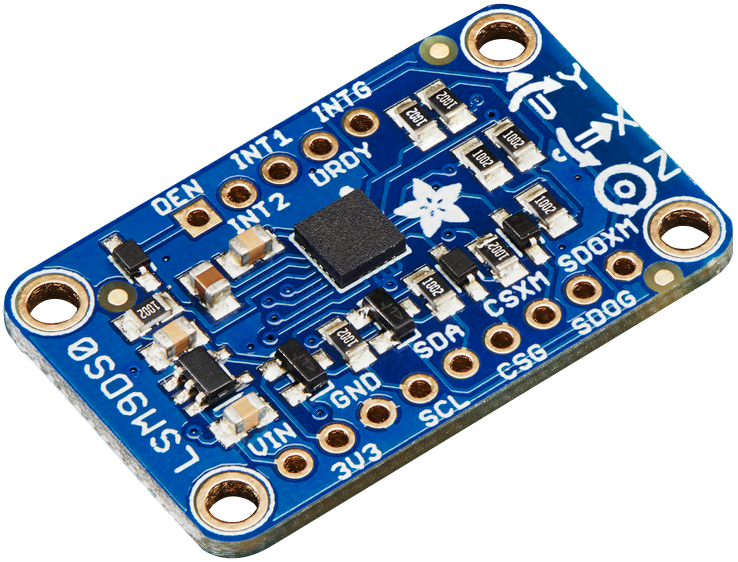
LSM9DS0 - I²C 3 Axis Accelerometer, Magnetometer and Gyroscope
Inside the chip are three sensors, one is a classic 3-axis accelerometer, which can tell you which direction is down towards the Earth (by measuring gravity) or how fast the board is accelerating in 3D space. The other is a 3-axis magnetometer that can sense where the strongest magnetic force is coming from, generally used to detect magnetic north. The third is a 3-axis gyroscope that can measure spin and twist.
More information
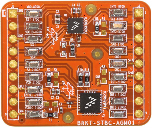
FXAS21002C - I²C 3 Axis Gyroscope
FXAS21002C is a small, low-power, yaw, pitch, and roll angular rate gyroscope with 16 bit ADC resolution. The full-scale range is adjustable from ±250°/s to ±2000°/s. It features both I2C and SPI interfaces.
FXAS21002C is capable of measuring angular rates up to ±2000°/s, with output data rates (ODR) from 12.5 to 800 Hz. An integrated Low-Pass Filter (LPF) allows the host application to limit the digital signal bandwidth. The device may be configured to generate an interrupt when a user-programmable angular rate threshold is crossed on any one of the enabled axes.
Measuing Revolutions
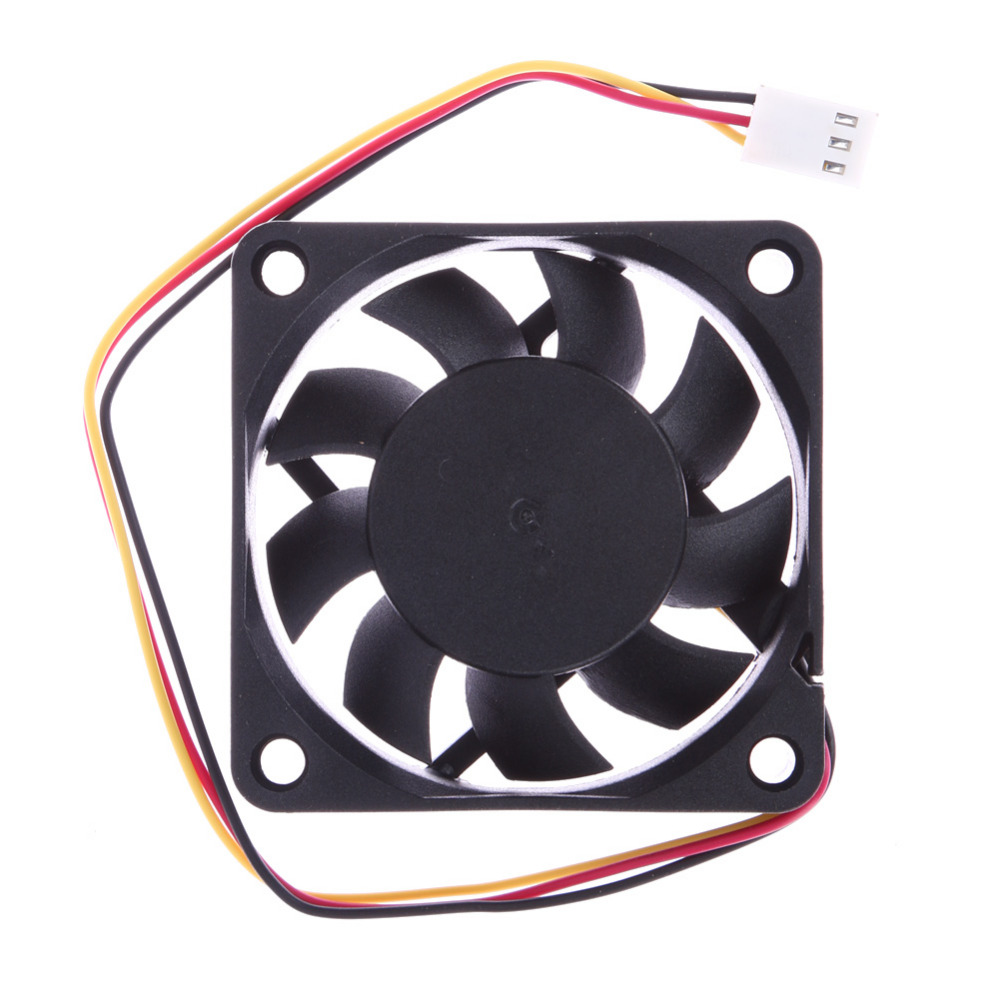
3 Wire Fans - GPIO Sensor
3 wire fans have an extra OUTPUT from the fan to tell the (generally motherboard) what speed the fan is turning.
Wiring schemes
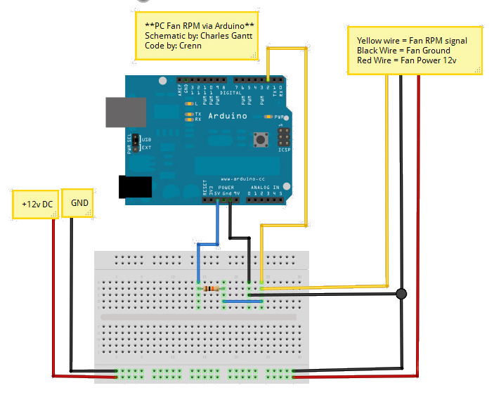
Measuring PC fan revolutions
4 Wire Fans - GPIO Sensor/PWM Actuator
4 wire fans have that same output as 3-wire fans, but also a PWM input pin that you can drive with a regular old pwm output pin from an arduino (or motherboard).
Measuring Soil Moisture
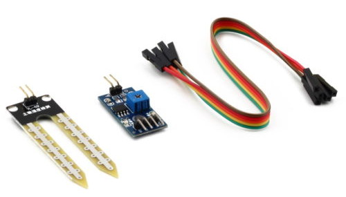
Hygrometer - GPIO/AIN Soil Moisture Sensor
Soil moisture sensors measure the water content in soil. A soil moisture probe is made up of multiple soil moisture sensors. One common type of soil moisture sensors in commercial use is a frequency domain sensor such as a capacitance sensor. Another sensor, the neutron moisture gauge, utilize the moderator properties of water for neutrons. Cheaper sensors - often for home use - are based on two electrodes measuring the resistance of the soil. Sometimes this simply consists of two bare (galvanized) wires, but there are also probes with wires embedded in gypsum.
Time domain transmission (TDT) and time domain reflectometry (TDR) is also used to measure moisture content; water has a high dielectric constant; a higher water concentration causes a higher average dielectric constant for the soil. The average dielectric constant can be sensed by measuring the speed of propagation along a buried transmission line.
More information
Where to buy
Xiaomi Mi Flora - BLE Gardening Sensor
The Mi Flora plant sensor is a small Bluetooth Low Energy device that monitors the moisture and conductivity of the soil as well as ambient light and temperature.
Measuring Temperature
A temperature is a comparative objective measure of hot and cold. It is measured, typically by a thermometer, through the bulk behavior of a thermometric material, detection of heat radiation, or by particle velocity or kinetic energy. It may be calibrated in any of various temperature scales, Celsius, Fahrenheit, Kelvin, etc.
MCP9808 - I²C Temperature Sensor
This I²C digital temperature sensor is one of the more accurate/precise we’ve ever seen, with a typical accuracy of ±0.25°C over the sensor’s -40°C to +125°C range and precision of +0.0625°C. They work great with any microcontroller using standard i2c. There are 3 address pins so you can connect up to 8 to a single I2C bus without address collisions. Best of all, a wide voltage range makes is usable with 2.7V to 5.5V logic.
More information
Where to buy
BMP180 - I²C Temperature and Pressure Sensor
See Air pressure chapter
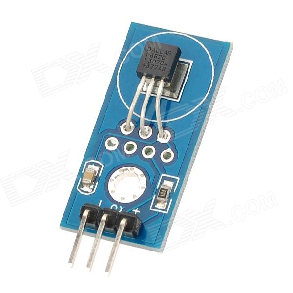
DS18B20 - GPIO Temperature Sensor
The DS18B20 is a rather useful sensor because you can read more than one of them using the same GPIO pin. Device is able to recognise the input from each separate sensor.
More information
- http://datasheets.maximintegrated.com/en/ds/DS18B20.pdf
- http://learn.adafruit.com/measuring-temperature-with-a-beaglebone-black
- http://designandmake.designspark.com/eng/projects/35/view/stage/design
- https://github.com/timofurrer/w1thermsensor
- http://www.bonebrews.com/temperature-monitoring-with-the-ds18b20-on-a-beaglebone-black/
- http://interactingobjects.com/ds18b20-temperature-sensor-on-a-beaglebone-black-running-ubuntu/
Where to buy
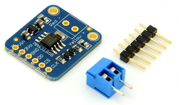
MAX31855 - I²C Thermocouple Amplifier
Thermocouples are very sensitive, requiring a good amplifier with a cold- compensation reference. The MAX31855K does everything for you, and can be easily interfaced with any microcontroller, even one without an analog input. This breakout board has the chip itself, a 3.3V regulator with 10uF bypass capacitors and level shifting circuitry, all assembled and tested. Comes with a 2 pin terminal block (for connecting to the thermocouple) and pin header (to plug into any breadboard or perfboard).
More information
Where to buy
- 15 EUR - http://www.hobbyelectronica.nl/product/thermocouple-amplifier-max31855/
- 15 USD - http://www.adafruit.com/product/269
- additional 10 USD - Thermocouple Type-K Glass Braid Insulated - http://www.adafruit.com/products/270
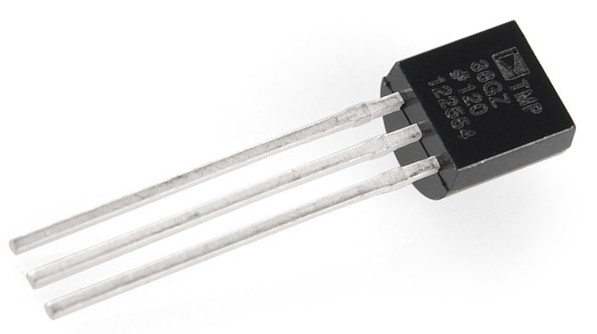
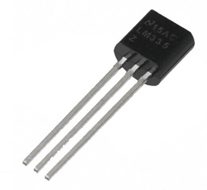
LM335 - AIN Temperature Sensor
The LM135 series are precision, easily-calibrated, integrated circuit temperature sensors. Operating as a 2-terminal zener, the LM135 has a breakdown voltage directly proportional to absolute temperature at 10 mV/°K. With less than 1-Ω dynamic impedance, the device operates over a current range of 400 µA to 5 mA with virtually no change in performance. When calibrated at 25°C, the LM135 has typically less than 1°C error over a 100°C temperature range. Unlike other sensors, the LM135 has a linear output.
More information
- GardenBot - The Soil Temperature Sensor http://gardenbot.org/howTo/soilTemp/
- http://www.ti.com/product/LM335
Where to buy
Measuring Multiple Metrics
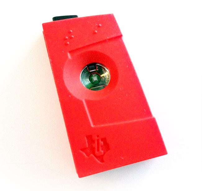
CC2541 SensorTag Kit
The SensorTag is fitted with six sensors and all sensors are chosen to be small, energy efficient and low cost surface mount devices. The sensors use I2C interface and are connected to the same interface bus with separate enable signals. To minimize current consumption all sensors are by default disabled and they are in sleep mode between measurements. Each sensor can be enabled and read individually. The SensorTag includes the following sensors:
- IR Temperature Sensor (TMP006) from Texas Instruments, http://www.ti.com/product/tmp006
- Humidity Sensor (SHT21) from Sensirion, http://www.sensirion.com/en/products/humidity-temperature/humidity-sensor-sht21/
- Pressure Sensor (T5400) from Epcos, http://www.epcos.com/inf/57/ds/T5400.pdf
- Accelerometer (KXTJ9) from Kionix, http://www.kionix.com/accelerometers/kxtj9
- Gyroscope (IMU-3000) from InvenSense, http://www.invensense.com/mems/gyro/imu3000.html
- Magnetometer (MAG3110) from Freescale, http://www.freescale.com/webapp/sps/site/prod_summary.jsp?code=MAG3110
More information
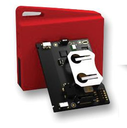
CC2650 SensorTag Kit
The new TI SensorTag is based on the CC2650 ultra-low power wireless MCU, offering a high-performance ARM® Cortex®-M3 and a fraction of the power consumption compared to previous Bluetooth® Smart products. It also includes cloud support, letting you move your sensor data from the smartphone app to the cloud with a simple touch on the screen.
Where to buy
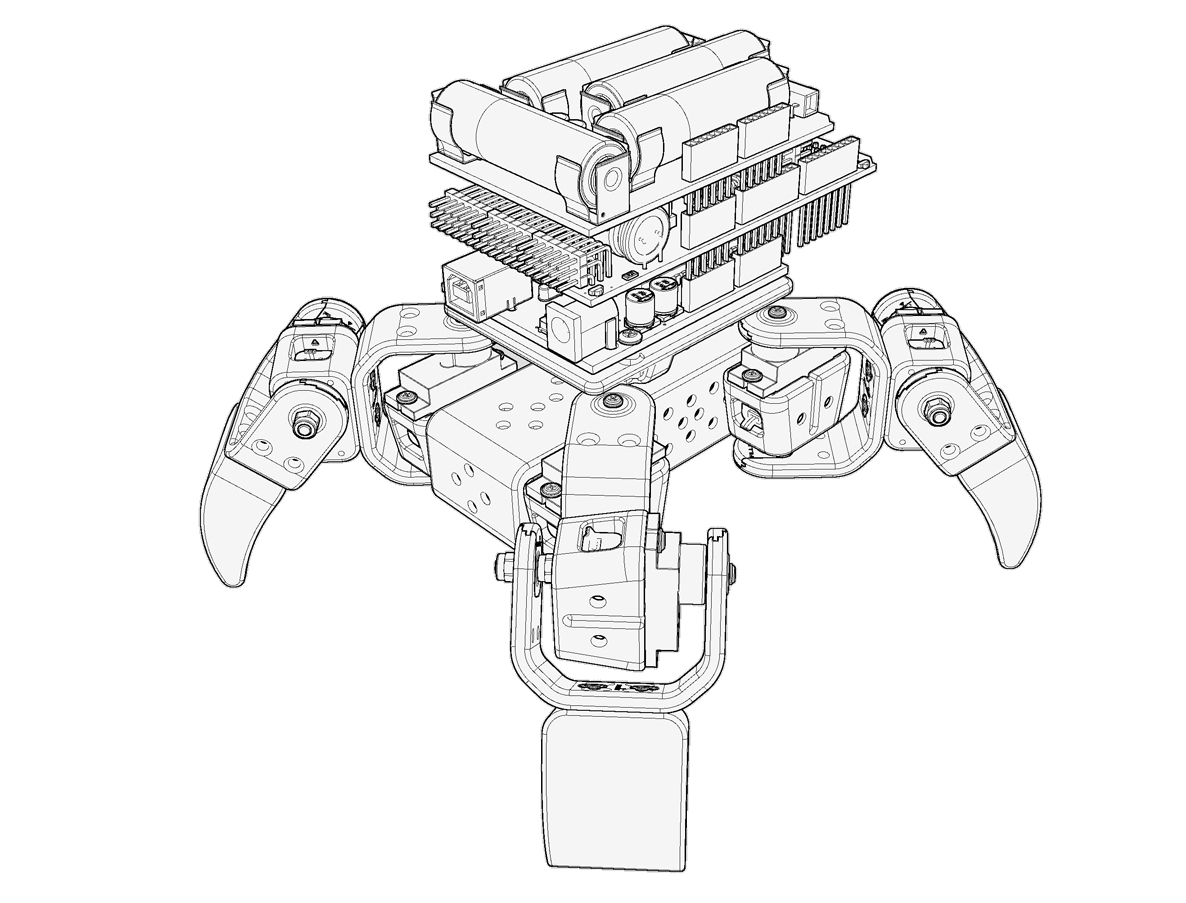
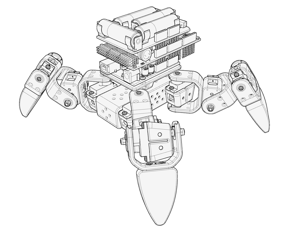
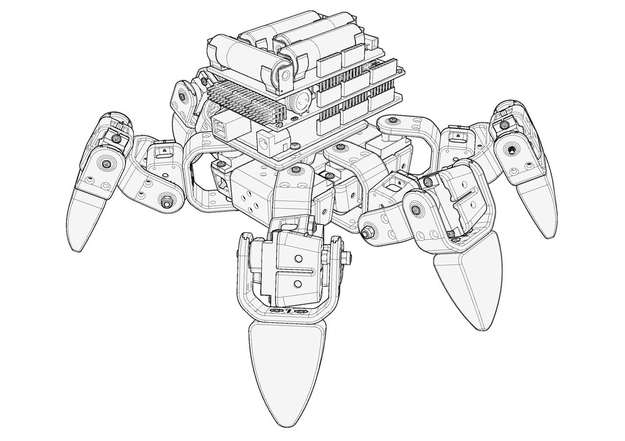
Chapter 7. Virtual Modules
Virtual devices represent module aggregation and are useful when encapsulating some higher logic (lean right at 6 legged spider) or make autonomous computation when communication layer goes down.
Ground Vehicle Legged
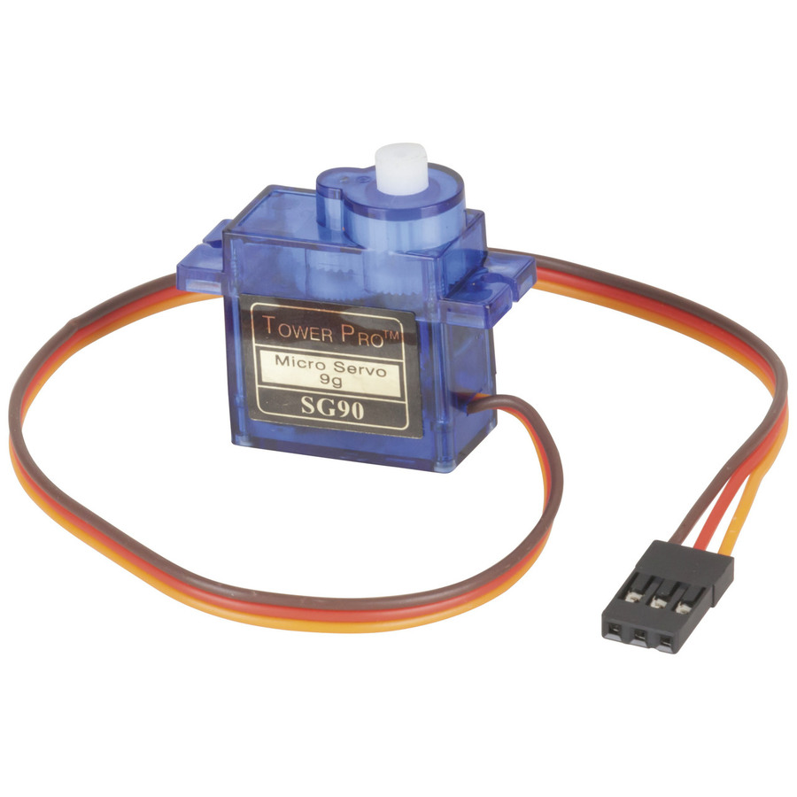
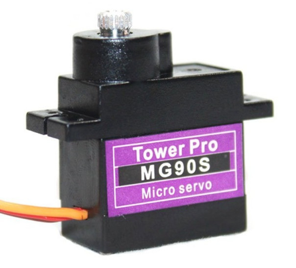
Allbot Spider 2 Legs/2 Joints - 4 PWM Servo Vehicle
Allbot Spider 4 Legs/2 Joints - 8 PWM Servo Vehicle
Allbot Spider 4 Legs/3 Joints - 12 PWM Servo Vehicle
Allbot Spider 6 Legs/2 Joints - 12 PWM Servo Vehicle
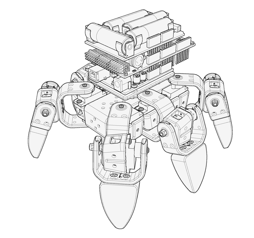
Allbot Spider 6 Legs/3 Joints - 18 PWM Servo Vehicle
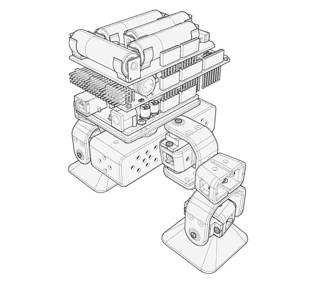
17DOF Bipedal Humanoid Robot - 17 PWM Servo Robot
The 17DOF Bipedal Humanoid Robot is completely assembled and ready to play. Robot could perform walking, squat, turning, side slide movements, and could dancing, fighting, or more complicated movements. Robot can feedback itself position.